Overcoming Wiring Problems
Written on: March 1, 2013 by Dan Auciello
With all the new energy saving boiler controls on the market, most coming packaged on the boiler, another challenge emerges. On Long Island, for example, the typical control wiring to the thermostat is 120 volts. It seems to be unique to our service area, and running new wires is usually not practical; using the existing 14 gauge wire (for 24 volts) is fine as long as you have the proper number of conductors. If you have a “home run” thermostat to boiler with two conductors, you are ok, but sometimes, we have three conductors present: L1, L2 and hot from the thermostat.

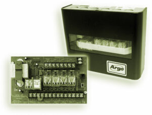
A typical multi-zone switching relay is this four-zone model, the ARM4P from Argo. Taco’s model SR504-4 is another good example.
In this case, we would leave the thermostat line voltage, then use a “RIB” relay to pull in dry contacts to activate our control system. Alternately, we can employ a separate step down transformer to activate that particular zone valve using the end switch as our dry contact.
When wiring a new system with several circulators, we need to use a multi-zone relay panel. This is where the other wiring challenge rears its ugly head. It was common to find a three-conductor wire at the boiler room to activate two separate zones, with one conductor as a common feed to both thermostats. At first, it may SEEM easy to jump the common conductor to another set of “TT” terminals on the zone panel, but this will cause many headaches, with back feeds, intermittent operation and excessive heat issues.
 There is a solution you will not find in any instruction manual. First, determine— with the power off— which “T” in the set of “TT” terminals is common. You can do this by simply using your ohm meter or continuity tester. The relay panel is powered by one transformer, so one side will terminate at the transformer common; you can even look at the back of the circuit board to see this. Now, you take the thermostat common and wire it to the first “T” you identified as the common in the panel.
You now have two conductors left from the thermostats. Connect the first zone to the second “T” on the first set of “TT” which is usually marked Zone 1 on the panel. The last conductor from the second zone thermostat connects to the second zone “TT” on the “T” terminal—THE ONE THAT IS NOT COMMON. This common terminal will not be connected to a wire since it is already connected internally. Make note that on some of the newer relay panels, the “TT” terminals are also designated “R” “W” with “W” as the common bond. This is not to be confused with some panels that also have a “C” terminal, providing 24Volts to power the thermostat through “R” and “C”. There are some affordable thermostats on the market that use the homeowner’s wifi to check and adjust settings remotely through the net and smart phones. Some need to have 24 volt power supplies through “R” “C” or through a separate transformer and will need a minimum of three conductors each thermostat for heat only. There are so many choices in controls today , we really need to stay ahead of the curve!

 There is a solution you will not find in any instruction manual. First, determine— with the power off— which “T” in the set of “TT” terminals is common. You can do this by simply using your ohm meter or continuity tester. The relay panel is powered by one transformer, so one side will terminate at the transformer common; you can even look at the back of the circuit board to see this. Now, you take the thermostat common and wire it to the first “T” you identified as the common in the panel.