Why Polypropylene?
Polypropylene is environmentally-friendly, designed for sustained flue gases up to 230°F (110°C) and provides performance properties better suited to handle flue gases than polyvinyl chloride (PVC) or chlorinated PVC (CPVC) technology.
The polypropylene flue gas vent system is specifically engineered for the intended application. Polypropylene has a vicat softening temperature that exceeds 300°F (meaning the temperature at which the thermal plastic deforms under the load). The polypropylene vent pipe has higher temperature ratings and enhanced corrosion resistance to the acidic properties of the condensate associated with high-efficiency appliances.
Unlike other polymeric or metal systems, polypropylene is resistant to aromatic hydrocarbons, sulfuric acid and hydrochloric acid, which allows it to be used with oil-, propane- and natural gas-fired high-efficiency appliances. It is only limited by the flue gas temperature, making it an ideal choice for condensing heating appliances.
Editors note: Polypropylene venting is also an ideal choice for oilheat non-condensing dilution air boilers, which run with appropriately low vent temperatures and are approved for use with polypropylene venting. Several systems have gained market acceptance in the United States for over a decade, and are also now rated for use with B20 fuel blends.
Polypropylene vent systems are manufactured specifically to perform as a vent system. All the various and necessary components, such as test ports, siphons and condensate drains, are available to install the proper vent system. There is no need to modify the vent system to analyze the combustion numbers or drain excessive condensate from the vent system. The manufacturers offer single-wall pipe, flexible pipe, as well as concentric pipe, so regardless of the structure type, the flue gases from the condensing appliances can be safely vented out of the building to the atmosphere.
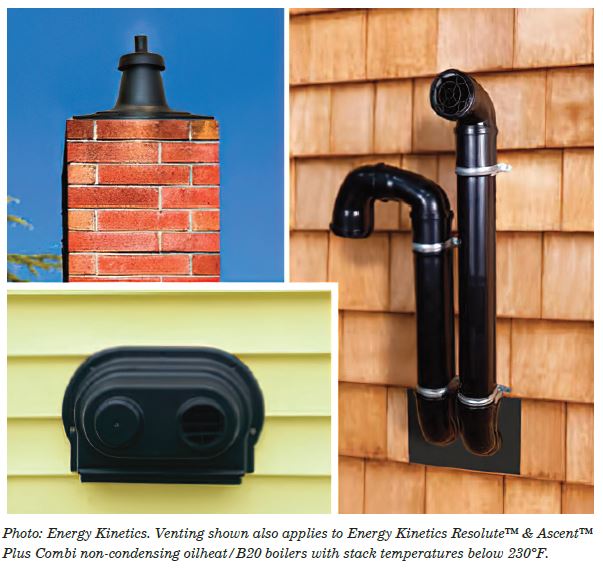
The polypropylene venting systems do not use glues and primers to join the lengths of pipes and fittings together. Instead they use a gasketed system to seal each connection point. The gasket technology allows the vent system to be installed rapidly; there is no need to rough-in the fittings as the components can be rotated in place, as well as disassembled. Once the venting system is completed, the high-efficiency appliance can be fired off immediately because, unlike glued systems, there is no 24-hour curing period required.
These polypropylene gas vent systems are designed to be used on condensing heating appliances that can produce one gallon of condensate per hour per hundred thousand British thermal units (BTUs). It is important that the vent system has proper pitch back towards the appliance, while the flue gases flow in the opposite direction towards the vent termination.
The pitch ensures that condensate is not allowed to build up in the vent system, which can cause back pressure leading to a forced shut down of the furnace or boiler. Also, build up of condensate gathering around a gasket can become a leak path, so good pitch allows the condensate to slide past each connection joint all the way back to the condensate trap.
A little history
Polypropylene gas vent systems have been around since 1994 for the European high-efficiency boiler market. The system is listed to the CE EN 14471 Safety Standard; the technology has proven to be safe and reliable. It is the dominating technology in Europe with millions of installations and is utilized by all the European heating equipment manufacturers.
This question comes up from time to time: Is PVC used for venting flue gases in Europe?
The answer is: No, Europe does not use PVC because of its lower maximum operating temperature and environmental health and safety concerns.
Manufacturers of these polypropylene gas vent systems arrived in the U.S. in 2009 and have sold and installed them for the last 13 years. One of the first things they did was obtain the UL-1738 listing to meet the most stringent and applicable safety standard used in the U.S.
Which leads us to the next question…Why UL 1738? The manufacturers of polypropylene gas vent systems had already been listed with Europe’s highest safety standard for venting flue gases from condensing appliances. They realized that, to participate in the U.S. market, they would need to be listed with the highest standard—Underwriters Laboratory-1738 (UL-1738). European manufacturers had an entire polypropylene vent system shipped to the lab to go through exhaustive testing procedures.
The reason why achieving a listing to the UL-1738 standard is so difficult is because there are several additional tests it puts the venting systems through that no other testing standards conduct:
Pressure Testing:
The vent system is tested to 250% of the rated operating pressure.
Leakage Testing:
The highest pressure is used to perform the leak test (3 L/H Max at 100Pa).
Low Temperature Handling:
A drop test is performed at -20°C (-4°F)—requiring no shattering, chips or cracks.
UV Testing:
This involves a 180-day UV Climate Chamber test.
High Temperature Testing:
The vent system is tested 70°F higher than the rated temperature.
Needless to say, the polypropylene gas venting system is a viable option to use when venting the flue gases from a high-efficiency condensing appliance. Because it uses a gasketed technology and not a glued technology, there are some installation details that are very different from what the industry may have been used to over the years. That is why the provision of installation instructions is the most important requirement of gas venting systems manufacturers wanting to be listed with UL-1738. Per the Standard, “Installation instructions shall be illustrated and include directions and information necessary to complete the intended installation of the venting system.” Can you imagine that? ICM
If you have any questions or comments, E-mail me at gcarey@fiainc.com, call 800-423-7187 or follow @Ask_Gcarey on Twitter. ICM 
Over the last 10–15 years, installing high efficiency gas-fired condensing appliances has become quite common in residential and light-commercial applications. The industry has been moving towards higher efficiency products and utility companies have and will continue to offer rebate incentives to their customers to adopt this technology.
Question: What makes these appliances more efficient than the boilers and furnaces that are being replaced?
Answer: They intentionally condense the flue products that are created during the combustion process.
When a gas boiler or furnace is firing, the flame that is produced through the process called “combustion” passes through the heat exchanger. The other side of the heat exchanger is either air (if a furnace) or water (if a boiler), which absorbs this heat through conduction. The flue gases, which are the result of this combustion, are then vented out of the appliance through the vent piping (B-vent or a chimney), out of the building and into the atmosphere. The flue gases are hot enough that they remain in their gaseous state until they exit the building. It is this temperature of the flue gases that impacts the stated efficiency of the appliance.
As energy prices have become more of a factor all over the world, the heating industry has been looking for higher efficiency-rated appliances that will allow the consumer to get more bang for their buck. The manufacturers modified the design of their heat exchangers so that they could condense the hot flue gases that normally would pass through the vent system and out to the atmosphere. By condensing the gases (changing the flue products from a gas to a liquid), latent heat is released, which increases the efficiency of the appliances up to an additional 10%! When these flue products turn back to condensate (a liquid), the liquid is very acidic and corrosive, which is why most appliance manufacturers have chosen stainless steel as the material to use when designing and building their heat exchangers.
Venting materials
Not all of the flue gases will condense while in contact with the heat exchanger and will enter into the venting system. The industry quickly learned that the traditional vent materials (B-vent, masonry and clay chimneys) could not withstand the acidic nature of the condensate. Manufacturers then started looking for other materials to use that would withstand the corrosive condensate. Stainless steel vent pipe was an obvious choice, but also quite expensive. Plastic pipe was the other option that the industry selected as an alternative to handle the acidic condensate. The plastics included pipes made of polyvinyl chloride (PVC), chlorinated polyvinyl chloride (CPVC) and polypropylene (thermoplastic polymer, PP). They are all classified as plastic pipe but each one has its own characteristics based upon its chemical makeup.
North American appliance manufacturers immediately adopted PVC, CPVC and stainless steel as their suggested vent pipe materials for their condensing products. PVC became the more popular vent pipe material of choice because it was the least expensive and readily available. In addition, every wholesaler in the plumbing and heating business had it in their inventory. Besides, plumbers were already accustomed to using it for most of their plumbing jobs.
Europe decided to go in a different direction. They chose polypropylene for their venting material to handle the flue gases for condensing boiler installations. One big difference to point out is that the polypropylene vent pipe was manufactured for one purpose—to vent the flue gases from these condensing appliances. The manufacturers engineered the vent pipe to be assembled as a complete venting system—from the appliance all the way to the termination. The manufacturers in Europe never considered using the other plastic piping (PVC or CPVC) to vent the condensing flue gases.
As European boiler manufacturers gained market share in the Northeast, and the condensing boiler market developed due to rising energy costs and rebate incentives offered by the utilities for higher efficiency appliances, polypropylene manufacturers decided to enter the North American market. Realizing that most contractors and wholesalers didn’t know who or what polypropylene piping was, the manufacturers needed to establish some credibility with their product. They approached Underwriter’s Laboratories (UL) and asked to test their highest venting standard in the U.S. UL1738 is considered to be the most stringent safety testing standard in the U.S.
In our next issue, we will discuss how this polypropylene venting system actually works, the benefits of using this type of venting system and answer some of the frequently asked questions about why gaskets (instead of glue) are used to seal each joint.
If you have any questions or comments, e-mail gcarey@fiainc.com, call 800-423-7187 or follow me at @Ask_Gcarey on Twitter. ICM
The heating industry has been focusing on improving the combustion efficiency of the boiler, and every boiler manufacturer has a modulating/condensing boiler in its product offering. The number of mod/con boiler installations has been growing every year and will continue to grow. Some of the boilers, when installed in the right application, are achieving efficiencies in the 95%+ range.
Some in the industry are under the impression that, with thermal efficiencies this high, there isn’t any room left to improve a hydronic heating system. Their thinking would be correct if combustion efficiency was the only goal. However, there is another efficiency that the industry is starting to look at—hydraulic efficiency of the distribution system. We should be looking at overall system efficiency, which includes how efficient the boiler plant converts fuel into heated system water and how efficiently this heated water is delivered to the building.
Definitions
Let’s first define what Distribution Efficiency is:
EFFICIENCY = Desired OUTPUT quantity/ Necessary INPUT quantity
In basic terms…how much energy is needed to get the desired output?
When we apply the definition of distribution efficiency to a heating system, it looks like this:
DISTRIBUTION EFFICIENCY
= Rate of heat delivery/ Rate of energy use by distribution equipment.
If a heating system provides 120,000 British Thermal Units/hour (BTU/H) at outdoor design conditions, and they have four circulators that consume 90 watts each, the Distribution Efficiency for that system is:
DE = 120,000 BTU/H/ 360 watts = 333 BTU/H / watt
Compare that to a warm air furnace where the blower motor consumes 1,050 watts while delivering 110,000 BTU/H through the duct system. The Distribution Efficiency for that system would be:
DE = 110,000 BTU/H / 1,050 watts = 105 BTU/H/ watt
The hydronic system has a higher Distribution Efficiency than the warm air furnace because the physical properties of water are much better for conveying heat than air.
Even though hydronic systems generally have a higher Distribution Efficiency than air systems, when the number of pumped zones increases, the Distribution Efficiency can quickly dissolve. For example, I recently visited a very large home that had 34 zones, all with water-lubricated circulators consuming 90 watts each. The house had a design load of 350,000 BTU/H. When you run the numbers to determine the Distribution Efficiency:
DE = 350,000 BTU/H / 34 x (90 watts) = 114 BTU/H / watt
As you can see, a hydronic system, when taken to the extreme, can become an inefficient distribution system. These systems have been installed for years with no real concern for operating costs. However, with energy costs continuing to rise, not only has it has impacted both fuel costs for transportation and heating homes, but electrical costs are also impacted.
Electrical power plants need to use some source of energy. The majority of plants have used coal for years, but through legislation, many are being closed down or converted to natural gas. This is putting tremendous pressure on the power plants to manufacture electricity. The result? Higher electric bills!
Over in Europe, where they have experienced higher fuel and electric costs, they have been forced to come up with better and more efficient ways to heat water and deliver the heated water to the heating terminal units. One of the technologies they have embraced for years is electronically commutated magnetic
motors (ECM).
The majority of residential homes in Europe use hot water heating to warm their homes. To achieve higher Distribution Efficiencies, they have incorporated ECM technology into their circulators. In fact, nowadays, only ECM circulators are allowed to be installed in Europe.
The pump manufacturers in Europe have combined their efforts to improve the efficiency of the circulators they offer for hot water heating systems. They came up with an efficiency index that all pump manufacturers had to reach called the Energy Efficiency Index (EEI). The European community created legislation to adopt this EEI standard and manufacturers quickly realized they could not achieve the necessary efficiency points with induction motor technology. It just proved to be too inefficient, so they moved to ECM technology.
Back in the Northeast
Utilities in the Northeast are providing rebate incentives for residential ECM circulators. It seems they are very interested in having the hydronic industry move away from the old, inefficient induction motors and move towards ECM technology. Plumbing and heating wholesale distributors have signed up and became part of the utility’s high-performance circulator program. This allows them to offer a $100 discount off the price of any of the participating ECM residential circulators.
Why would they provide such a generous incentive? It has to do with energy costs and energy consumption. As energy costs continue to rise, the impact affects everyone. As production costs go up, distribution costs go up, and the net result is higher utility bills for end-users.
If we were to re-examine our Distribution Efficiency formula while incorporating the new ECM circulators that can consume considerably fewer watts, the Distribution Efficiency can be markedly improved. If we go back to that large home that had 34 water-lubricated zone pumps and replaced them with the ECM pumps with speed control (which allows the pump to be set for the zone’s actual load) the formula would look something like this:
DE = 350,000 BTU/H / 34 x (20 watts) = 515 BTU/H / watt
If you have any questions or comments, e-mail gcarey@fiainc.com; call 1-800-423-7187 or follow @Ask_Gcarey on Twitter. ICM
Circulators have been around the hydronic heating industry dating back to the late 1920s to the early 1930s. They were originally added to existing gravity hot water jobs to “boost” the heat around the system. In fact, Bell & Gossett marketed its circulators as “Booster” pumps because they would move the heat from the boiler to the radiators much faster than simply by gravity.
These original circulators were often referred to as “three-piece” pumps because they had three distinct sections—the wet end or volute where the impeller is located; the motor end (which is the driving force) that would mount in a cradle; and a bearing assembly that would connect the two ends together with a coupling assembly. The motor assembly was completely separated from the wet end of the pump by a seal. The bearing assembly would be lubricated with oil to keep the bearings in good working condition. These pumps dominated the hydronics industry for decades and did a very good job.
Sometime in the 1970s or early 1980s a new style of pump came onto the scene that changed forever the residential (and eventually light commercial) market. These “new” circulators used the system’s own water as its lubricant. There was no longer a need for a separate bearing assembly and seal. The physical size of these pumps was considerably smaller and they cost much less than the three-piece style. At first, there were many skeptics about the new pump’s ability to perform as well as the original, larger pumps. However, over time, the industry realized these new “water-lubricated” pumps worked quite well, lasted a long time, required virtually no maintenance and were less expensive.
Over the past 10 years, some pump manufacturers have been offering multi-speed pumps that offer a different pump curve for each speed. The most common is a three-speed wet-rotor circulator that offers three different performance curves. The benefit is that, with one pump, you can provide three different curves to meet various system conditions. From an inventory standpoint, you can stock (on the shelves or in the service truck) one circulator model that can meet many different system applications.
Imagine 10 speeds or even 50 speeds instead of just three speeds—and for each speed change, you could plot a new pump performance curve. The highest speed would represent the pump’s maximum performance and the lowest speed would represent the pump’s minimum performance. A variable speed pump can operate anywhere between these two points simply by varying the speed of the motor.
Any wet rotor pump with a permanent split capacitor motor can function over an extensive range of speeds with a variable speed controller. This device varies the frequency of the alternating current (AC) signal sent to the permanent split capacitor (PSC) motor. By varying the AC signal, the rotations per minute (RPM) of the motor (the speed) are changed, which directly changes the flow and head capacity of the pump. The changes, and therefore the pump curves, are unlimited between the fastest and slowest RPMs of the motor. One popular application uses a standard wet rotor pump controlled by one these variable speed controllers to provide injection mixing for any low-temperature heating system.
The new circulator—ECM
A new style of “smart” pumps has made its way into the North American hydronics market. They are called ECM pumps, which stands for electronically commutated magnetic motor. They are very different from the PSC motors we have been using in our wet rotor pumps. This new style motor is sometimes called a “brushless DC” motor. The rotor in this ECM motor has permanent magnets instead of wire windings that are separated from the system fluid. The magnets are located inside a stainless-steel rotor can and react to the magnetic forces created by electromagnetic poles in the stator.
Here is where you may experience a problem with the new ECM circulators. These onboard magnets can do a very good job of collecting/attracting iron oxide from the water in the system. Iron oxide is a chemical compound consisting of a mixture of oxygen and iron. Every hydronic system has some oxygen (from the system water [H2O]), and more often than not, some type of iron, ie.; cast iron from circulator volutes, flow-control valves, cast iron boilers, cast iron radiators and black iron steel pipe.
Every system can contain a different amount of iron oxide, which will influence whether the ECM circulator “attracts” enough of it to cause the pump to stop running. I have heard of several instances where the contractor isolated the pump, pulled the can from the wet end of the pump, cleaned off the buildup of iron oxide, put the pump back together and it ran fine afterwards. Other times they ended up having to replace the pump because too much damage had been done.
There is a simple solution to this and it’s not to go back to the old-style wet rotor pump—that horse has already left the barn. The utilities have been playing a big part in creating incentive programs to promote the installation of these “High Efficiency” pumps, similar to how they played a big part in the industry’s adoption of modulating/condensing (Mod/Con) boilers. Europe has been installing high efficiency boilers for years (having outlawed the PSC wet rotor pumps because they consume too much electricity) and installs high performance dirt and magnetite separators as standard design practice.
If you are installing high efficiency boilers and ECM pumps (by law), then you want to ensure the quality of the water circulating through the system. As the industry continues to install these high efficiency ECM pumps, it should become standard practice to also include a magnetic dirt and iron oxide collector to protect the new high efficiency equipment.
The efficiency of these “Greener” circulators was designed to meet the ever-increasing efficiency standards that have made their way over to North America. Their “wire to water” efficiency is simply higher than the PSC wet rotor circulators. Their multiple application capabilities with the onboard microprocessors and their reduction in wattage consumption make them a very compelling alternative to what we have used in the past. ICM
If you have any questions or comments, e-mail gcarey@fiainc.com, call 800-423-7187 or follow @Ask_Gcarey on Twitter.
There have been many condensing boilers installed during the past few years that operate with natural or propane gas as their fuel source. They are called “high-efficiency” boilers because they have efficiency ratings in the 90s…some as high as 95%. To attain such high efficiency numbers, they intentionally condense some of the flue products that are formed as the result of combustion.
Normally, we would make sure that the boiler never condenses its flue products because, if allowed to, the condensate could damage the boiler and vent piping. When combustion occurs, energy in the form of heat is transferred through a heat exchanger (pinned cast-iron sections, copper-finned tubes, cast-aluminum and stainless-steel heat exchangers) to flowing water, which is on the other side of the flame. When the flame is produced, combustion gases are formed. These gases contain water in the form of vapor.
Generally speaking, we want these vapor gases to vent out of the boiler, up into the venting/chimney system and out into the atmosphere. Condensing boilers are designed to allow the flue gases to condense right inside the heat exchanger. They even provide a condensate drain to allow the condensate to escape from the heat exchanger and drip through a neutralization kit into a drain or condensate pump.
The benefit of condensing these combustion gases is that they contain heat or energy that we normally lose up the chimney. Just like in a steam system, when the water in the form of vapor (combustion gases) condenses, it gives off a lot of latent heat. How much? For every pound of water vapor that condenses back to liquid, 1,000 BTUs of latent heat are released. The heat exchanger “catches” this heat and transfers it over to the system water. This is how these condensing boilers achieve higher efficiency ratings. More of the unit of fuel goes into heating the system water rather than up the flue pipe.
Inner workings
Just how are these flue gases condensed? It is the exact opposite method of how we prevent these same gases from condensing in a non-condensing boiler. Condensing occurs naturally—when the combustion vapors cool below dewpoint, they will condense back to liquid. Water temperature has the greatest impact on whether the flue gases in a boiler will condense or not. It’s all related to the dewpoint of the combustion gases. Oil-fired systems want to keep the water above 140°F to prevent the gases from condensing, while gas systems generally want to be above 130°F to prevent condensing.
In a condensing boiler, the water temperature in the return needs to be 130°F or less for the flue gases to condense. With return water in that temperature range, the flue gases will condense and the boiler will operate at or near the published efficiency rating. Whenever the return water climbs above 130°F, which is higher than the dewpoint of the combustion vapors, those gases will not condense in the heat exchanger.
The particulars
The question often is, Can I use a high-efficiency modulating and condensing boiler in a system that incorporates traditional high temperature baseboard? Some people in the industry would say, No you can’t! The water needs to be hot enough to satisfy the baseboard’s requirements, which are too hot to allow any condensing of the flue gases! If you aren’t condensing the flue gases, why use a condensing boiler?
A large portion of these condensing boilers are sold in retrofit applications for both residential and commercial buildings. The boilers usually are cast iron oil-fired or atmospheric vented gas boilers and they serve high temperature terminal units such as copper baseboard or cast iron radiators.
When these systems were first installed, the radiation was sized so that on a design cold day, with water circulating through the radiation at 180°F, the room temperature could be maintained at 70°F. Due to these design conditions, the above comments can be made about compatibility issues between condensing boilers and baseboard radiation.
However, how often during the heating season do we actually encounter design conditions? Up here in the Northeast, design conditions make up about 3–5% of heating. The conditions are somewhere less than design during the rest of the year. In fact, through Bin Data collected by the National Weather Bureau, 80% of the heating season requires 50% or less of the BTUs needed for design conditions. In effect, the heating system, including the boiler and the installed radiation, is oversized for most of the heating season.
Proper application of Outdoor Reset
Outdoor Reset calculates the right water temperature for the radiation based upon the load that the house or building is experiencing. What has the greatest impact on a building’s load? The outdoor temperature! By simply incorporating the outdoor reset function that comes with the condensing boiler’s operating control, the boiler can start delivering the appropriate water temperature needed at the given set of outdoor conditions.
As you look into design conditions, reset curves and Bin Data, you see that for a large majority of the heating season, the boiler can lower the water temperature so the return temperatures coming back to the boiler are below combustion gas dewpoint levels. The boiler flue gases are now condensing; the boiler is operating at or near its rated efficiencies and the apartment building or house is comfortable.
When designing around 180°F water, 70°F indoors and a design outdoor temperature of between 0°F and 10°F, you will find that, until it gets down to 25°F or colder, the reset curve will calculate a water temperature that provides return temperatures below the dewpoint of the flue gases, ensuring the boiler is operating in a condensing mode.
Another benefit to this style of boiler is that, in addition to the condensing feature, the burner can modulate. This means that as the load changes, the boiler will consume only the necessary fuel to meet that load. Unlike traditional “On/Off” boilers—where, if they are firing, they are consuming 100% capacity—the modulating boiler can fire down to as low as 10% of its capacity and then modulate all the way up to 100%.
In a perfect situation, when using a condensing boiler, the radiation chosen should be able to provide all the BTUs needed with low temperature water. For that to occur, all of the existing homes and commercial buildings would have to change and/or upgrade their existing radiation. In some rare instances, that actually does happen—but the majority of the time it doesn’t.
Will the boiler condense all the time? No, but it will for the majority of the heating season. It will also modulate its firing rate to match the load that the building is experiencing. All of these features add up to reduced fuel consumption and more comfortable heating systems. If you have any questions or comments, e-mail me at gcarey@fiainc.com or call me at 1-800-423-7187. ICM
In the past, underground snow melting of a driveway or walkway for residences had been considered a luxury and perceived as too expensive to install and operate. However, over the years, I’ve seen the number of snowmelt systems installed in residential homes increase quite a bit. The scenario may have been renovation of an existing home that included replacing or upgrading the driveway or it may have been part of a newly constructed home’s design.
Regardless of the situation, it has become increasingly common to install a snow melt system but, unlike other traditional heating systems, once the tubing is installed and piped, it is fairly difficult to fix a design flaw. This is why I find the quote from Bell & Gossett as relevant today as it was 56 years ago: Snow melting systems have been used for many years in commercial installations such as store front walks, parking garage ramps, loading docks, etc. In these installations the protection against slippery pavement is complemented by the elimination of tiresome and messy jobs of snow shoveling or plowing.
The benefits of snow melting systems can carry over into the residential field quite easily. The necessary equipment for a well engineered snow melting system is easily adaptable to any standard hot water boiler. Two of the major limitations to wider acceptance and use of snow melting systems are cost and lack of proper design information. These two characteristics go hand in hand. (1966 Bell & Gossett Snow Melting System Design Manual).

Snowmelting does have some design issues, as well as operating issues, that both you and your customer need to discuss. First, once the customer gets past the installation cost, the next question is always: How much does it cost to operate? The answer depends on a lot of issues, such as how much snow needs to be melted, how quickly it needs to be melted, if the customer “idles” the driveway at some minimum temperature and how cold it is outside. Based upon some standard conditions here in the Northeast, the following example can be used to approximate what it may cost to operate your snowmelt system during a snowstorm. If you have a 1,000 square foot driveway and the snowmelt system provides 200 British Thermal Units (BTUs)/hour per square foot surface area, you would need a boiler capable of providing at least 200,000 BTU/h. In our example, the snowmelt system ran for 10 hours to melt the driveway, so you would consume 20 therms of natural gas or about 16 gallons of oil. Based on the cost of either a therm of natural gas or a gallon of No. 2 fuel oil, you could calculate the cost to melt the snow during that single event.
Controlling the melt
How the snowmelt is controlled plays an important part in the cost to operate the system. There are many ways of operating a snowmelt system. They can be turned “on” and “off” manually, automatically and somewhere in between. From an economic standpoint, the system should start as soon as it detects snowfall and turn off as soon as the snow is melted off the driveway. This is probably the least expensive way to operate and still maintain all the benefits of a snowmelting system.
You will want to have a conversation with your customers regarding the expectations they have on what they think their snowmelt system can (and can’t) do. Some people think that when it starts snowing, they can invite their friends over for a snowmelt party. You will want to make sure they understand there is a “time-lag”— it takes time for the snowmelt system to heat up the slab and bring it up to a melting temperature. Once it reaches the melting temperature, the system will continue to run until the automatic snow/ice sensor senses that it is dry and shuts the system off until the next snow fall. This operation may last 4–5 hours and quite possibly longer depending upon the amount of snowfall, how long the storm lasts and the outdoor temperature. You will want your customer to understand this up front, before the first snowfall.
In some applications (usually commercial and industrial), customers can’t wait that long for the snow melt system to activate. Instead, they operate the system in what’s known as an “idling” condition. Most snowmelt controls have a feature where you can set the snow/ice sensor to maintain the slab at some minimum temperature, typically 33–35°F. This gives the snowmelt system a “running start” so that when the snow starts falling, the slab does not have to be heated from a cold starting point.
This, of course, costs money. You are heating a slab all the time, so regardless of outdoor temperatures and wind speeds, you are “pumping” BTUs into the ground. This is another thing your customers need to know when discussing their expectations of the system.
Designing the system
In a residential application, a snowmelt system is a convenience item. You don’t have to wait for the plow guy to show up; you don’t have to shovel the driveway; you don’t have to salt your driveway and walkway and the system can start and stop automatically. However, it does take some time to get up and going before the melting starts.
From a design standpoint, you can use any of the radiant tubing manufacturers or their representatives to help you design and lay out the system. They will be able to help you calculate the actual load, select the right size and amount of tubing, how to best lay out the tubing, the correct design water temperatures, as well as offer a control and piping strategy to operate the system.
In general, there are a few design issues that should concern you. The first issue is if you are going to use the existing boiler to melt the snow. Does it have the capacity to handle this extra load? If not (probably the case in most systems), are you going to dedicate a boiler to just snow melt? This does happen often, but I think a better design is to add the additional boiler to the existing boiler, piped as a multiple boiler plant. Then by adding a plate and frame heat exchanger, which is dedicated to the snow melt system, you can have backup capabilities, rotation and all the other features that come with a multiple boiler system.
When the snowmelt system first turns on, it is very important that the slab/driveway does not get “shocked” with hot water. The control system has to monitor the heat input to the slab in a controlled manner to protect the slab. If not, the driveway will possibly experience cracking. The same issues exist in the boiler room. It is important to prevent large slugs of extremely cold water from entering the boiler(s). This could cause thermal stressing and eventual cracking of boiler sections.
If standard, non-condensing boilers are used, the control system has to prevent flue-gas condensation from occurring for extended periods of time. If not, the system will damage the flue piping and eventually the cast-iron sections. All of these issues can be handled easily with proper piping and a proper control strategy. Again, something that the radiant tubing manufacturers deal with in every system they design.
If you have any questions or comments, contact me at gcarey@fiainc.com or 1-800-423-7187. ICM
Mother Nature has a collection of “rules” that govern how things work in this world—“High pressure goes to low pressure,” “Whatever goes up must come down,” “For every action there is an equal and opposite reaction” and probably her most famous if you are in the heating industry, “Heat goes to cold!” If you were to ask someone where does heat go? he/she would say heat rises. That’s not necessarily correct, since hot air rises, but heat goes to cold, always. Mother Nature hates an imbalance and, when it exists, she does everything in her power to equalize or balance it.
When your heating system delivers warmth to your house, it eventually leaves through the windows, roof and siding. Why does the heat leave? There is an imbalance between the temperature inside the house and the temperature outside. Heat goes to cold…always! The same thing happens in the Summertime. When it is very hot outside and your house is cooler inside, the heat outside wants to go to the cooler indoor temperature.
How do we typically make the indoor cooler? Most people would say the air conditioner, which is true, but how eludes most people. We use an air conditioning system that removes heat from the indoors and sends it outside. That’s because you can’t make cold. To create a cooler atmosphere, you have to remove the heat, which is the basis of refrigeration. Whenever you feel cold, it is caused by a lack of heat.
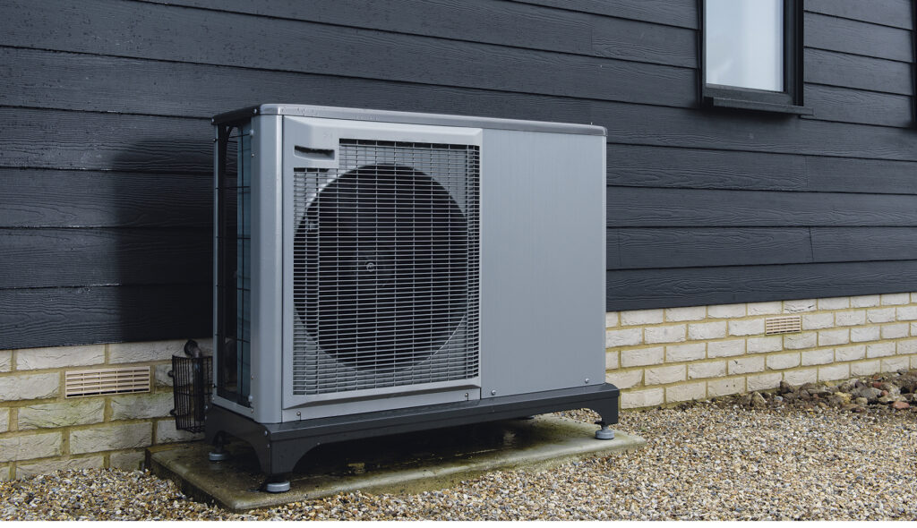
If we know that heat wants to go to cold, why do we call it a heat pump? Why do we have to pump the heat when heat normally goes to cold? The reason is a heat pump, rather than creating heat, simply moves it. For example, it can move thermal energy from the cooler outdoor air into the warmer inside room. It pushes heat in a direction counter to its normal flow (cold to hot rather than hot to cold), hence the word pump. A boiler or furnace burns fossil fuel to create heat. A heat pump simply uses an existing source of renewable energy, like the heat that exists in outdoor air. This can lead to a significantly reduced consumption of energy while providing comfort.
Refrigeration
The definition of Refrigeration is the process in which work is done to move heat from one location to another. It may also be defined as lowering the temperature of an enclosed space by removing heat from that space and transferring it elsewhere.
Refrigeration uses refrigerant to move heat as it changes state. Nowadays, the refrigerant of choice is R410A. Its properties allow the refrigerant to be a liquid well below freezing. It has a freezing point at -155°C which is equivalent to -247°F. It has a boiling point of -48.5°C which is equivalent to -55°F. As a liquid refrigerant, it absorbs heat when it evaporates into a vapor. When the refrigerant is in its vapor state, it contains all that energy; when it condenses back into a liquid, it rejects or expels the heat it originally absorbed.
You have to remember that phase change contains a significant amount of energy. For example, when you change the temperature of one pound of water from 211°F to 212°F, it requires one British Thermal Unit (BTU). When you change one pound of 212°F water to 212°F vapor (steam), it takes 970 BTUs that you “get back” when the vapor condenses back to its liquid state.
A heat pump incorporates the vapor-compression refrigeration cycle to move heat either away from an area where it’s not wanted (cooling) or moves heat into a space that needs it (heating). Because of the unique operating properties of R410A, an Air-to-Water or Air-to-Air heat pump has the ability to take heat (energy) out of the air that we would consider very cold but to the refrigerant considers it warm. This applies to the heating mode of the heat pump.
The cooling operation is identical to that of an air conditioner. Again, using refrigerant and the vapor-compression cycle, the cold liquid refrigerant flows through the air conditioning coil as room air blows across it. The heat from the air goes to the cold liquid refrigerant, thus leaving the air cooler than it was when it entered the coil. The absorbed heat “flashed” the cold liquid refrigerant into cool vapor, which will then flow outside to the compressor. There, the cool vapor will be compressed (by the compressor) into a high temperature vapor. The vapor, which is storing a lot of energy (the heat we wanted to remove from the home), is pumped through a condensing coil where a fan is blowing outside air across it. This outdoor air is hot, relative to our comfort, but much cooler than the temperature of the hot vapor refrigerant. The hot vapor transfers its energy/heat to the outside air, thus completing the process of removing heat from the house and condensing it back into a warm liquid.
Reversing valve
Heat pumps have the unique ability to either heat or cool a home through a simple device called a reversing valve. There are four key components required:
• evaporator
• condensor
• compressor
• expansion valve
By adding the reversing valve, the heat pump can “reverse” the role of these key components and provide heating or cooling from the same compressor.
Another term unique to heat pumps is Coefficient of Performance (COP). This term expresses how efficient the heat pump is with regards to the amount of energy it uses relative to the amount of energy it delivers. The term was developed to compare heat pump systems according to their energy efficiency. A higher value implies a higher efficiency between the pump’s consumption of energy and its output. Design conditions will impact the heat pump’s COP performance factor. Air-to-Air and Air-to-Water heat pumps have in the past been negatively impacted in their performance by colder outdoor temperatures. However, with advances in compressor technology, specifically invertor-driven compressors, these Air-to-Air and Air-to-Water heat pumps are capable of extracting energy (heat) from very cold outdoor temperatures and transferring the energy to the heating medium (water or air).
Contact me with any questions or comments at gcarey@fiainc.com; 800-423-7187 or follow me on Twitter at @Ask_Gcarey. ICM
Circulators have been around the hydronic heating industry since the 1930s. They were originally added to existing gravity hot water jobs to “boost” the heat around the system. These original circulators were often referred to as “three-piece” pumps because they had three distinct sections—the wet end or volute where the impeller is located, the motor end (which is the driving force) that would mount in a cradle and a bearing assembly that would connect the two ends together with a coupling assembly.
The motor assembly was completely separated from the wet end of the pump by a seal. The bearing assembly would be lubricated with oil to keep the bearings in good working condition. These pumps dominated the hydronics industry for decades and did a very good job.
Sometime in the 1970s, a new style of pump came onto the scene that changed forever the residential (and eventually light commercial) market. These “new” circulators used the system’s own water as its lubricant. There was no longer a need for a separate bearing assembly and seal. The physical size of these pumps was considerably smaller and they cost much less than the three-piece style.
At first there were many skeptics about the new pump’s ability to perform as well as the original, larger pumps. However, over time, the industry realized these new “water-lubricated” pumps worked quite well, lasted a long time, required virtually no maintenance and were less expensive.
Multi-speed pumps
Over the past 10 years, some pump manufacturers have been offering multi-speed pumps, which offer a different pump curve for each speed. The most common is a three-speed wet-rotor circulator, which offers three different performance curves. The benefit is that with one pump, three different curves are provided to meet various system conditions. From an inventory standpoint, you can stock—on the shelves or in the service truck—one circulator model that can meet many different system applications.
Imagine that instead of three speeds there are 10 speeds or even 50 speeds—for each speed change you could plot a new pump performance curve. The highest speed would represent the pump’s maximum performance and the lowest speed would represent the pump’s minimum performance. A variable speed pump can operate anywhere between these two points simply by varying the speed of the motor.
Any wet rotor pump with a permanent split capacitor motor can function over an extensive range of speeds with a variable speed controller. This device varies the frequency of the AC signal sent to the permanent split capacitor (PSC) motor. By varying the AC signal, the revolutions per minute (RPMs) of the motor (the speed) are changed, which directly changes the flow and head capacity of the pump. The changes, and therefore the pump curves, are unlimited between the fastest and slowest RPMs of the motor.
The new circulator: ECM
“Smart” pumps, the latest technology in pumping, have made their way into the North American hydronics market. They are called ECM pumps, which stands for “electronically commutated magnetic motor.” They are very different from the PSC motors we have been using in our wet rotor pumps. This new style motor is sometimes called a “brushless DC” motor. The rotor in this ECM motor has permanent magnets instead of wire windings that are separated from the system fluid. The magnets are located inside a stainless steel rotor can and react to the magnetic forces created by electromagnetic poles in the stator.
However, you may experience a problem with the new ECM circulators, as the onboard magnets can collect/attract iron oxide from the water in the system. Iron oxide is a chemical compound consisting of a mixture of oxygen and iron. Every hydronic system has some oxygen (from the system water H2O) and more often than not some type of iron (i.e. cast iron from circulator volutes, flow-control valves, cast iron boilers, cast iron radiators and black iron steel pipe).
Of course, every system can contain a different amount of iron oxide, which will influence whether the ECM circulator “attracts” enough of it to cause the pump to stop running. I have heard of several instances where the contractor isolated the pump, pulled the can from the wet end of the pump, cleaned off the buildup of iron oxide, put the pump back together and it ran fine afterwards. Other times they ended up having to replace the pump because too much damage had been done.
A simple solution
There is a simple solution to this and it is not to go back to the old-style wet rotor pump— that horse has already left the barn. The utilities have been playing a big part in creating incentive programs to promote the installation of “High Efficiency” pumps, just like how they played a big part in the industry’s adoption of modulating/condensing (Mod/Con) boilers.
Look to Europe, which has been installing high efficiency boilers for years and has outlawed PSC (permanent split capacitor wet rotor pumps) due to the fact that they consume too much electricity. Instead, they have been installing high performance dirt and magnetite separators for years.
It is just standard design practice over there—if you are putting in high efficiency boilers and ECM pumps (by law), then you want to ensure the quality of the water circulating through the system. As the industry continues to install these high, efficiency ECM pumps, it should become standard practice to also include a magnetic dirt and iron oxide collector to protect the new high efficiency equipment.
The efficiency of these “Greener” circulators was designed to meet the ever increasing efficiency standards that have made their way over to North America. Their “wire to water” efficiency is simply higher than the PSC wet rotor circulators. Their multiple application capabilities with the on-board microprocessors, and their reduction in wattage consumption, make them a very compelling alternative to what we have used in the past.
If you have any questions or comments, E-mail gcarey@fiainc.com, call 800-423-7187 or follow me on Twitter at @Ask_Gcarey. ICM
As I am writing this column, the summer of 2021 is getting underway. It seems like a strange time to talk about steam systems and condensate handling equipment, but as you all know, the heating season will be here before we know it, and steam systems will be turning on as the cool nights eventually arrive. Condensate pumps, when used in steam systems, play an important part in the proper operation of that system.
Understanding the operation of these pumps is pretty straightforward. The condensate pump is made up of a pump and motor with an impeller on the end of it, and a receiver that the pump and motor are mounted on (usually cast iron, but steel can also be used). Cast iron receivers are more rugged and last longer in corrosive environments; condensate usually has a low pH (which makes it acidic). Inside the receiver is a float assembly (not unlike a ballcock found in a toilet tank) that is connected to a floatoperated electrical switch, which is attached to the receiver. The receiver has an inlet opening near the top side of the receiver; it also has an opening on the top where a vent pipe is connected.
The condensate return piping from the system is connected to the inlet connection of the receiver; the vent pipe is used to vent the air from the system. As condensate and air travel along the return piping, they enter into the receiver through the inlet connection. The condensate falls to the bottom of the receiver while the air enters into the receiver and exits out through the vent pipe located at the top of the receiver.
Therefore, in effect, the vent pipe of the condensate pump is the main air vent for the system. Make sure that there are no water pockets in the return piping because that could prevent air from getting out of the system. Also, never plug the vent line because condensate pumps are not rated for pressure. If they become “pressurized” because of a blocked vent line, they could explode!
As the condensate continues to gather in the receiver, the float part of the assembly starts to “float” up/rise up with the rising level of condensate. At some point, the float-operated electrical switch “makes”—closing a set of contacts that turns the pump on. The condensate pump discharges the condensate to either the boiler directly or possibly to a boiler feed tank in the boiler room. Naturally, as the pump discharges the condensate from the receiver, the water level, as well as the float in the receiver lowers to a point where the switch “breaks.” This opens the contacts that turn the condensate pump off. This is basically what a condensate pump does—as returning condensate enters the receiver, it raises the float, which eventually turns the pump on. As the water level drops in the receiver, so does the float—eventually turning the pump off.
Important details
There are a couple of details that you need to pay attention to when piping a condensate pump into the system. On the inlet side of the receiver, it is good piping practice to install some type of strainer (a Y-strainer or basket strainer are two popular choices) just before the condensate enters into the receiver. There is sediment in old steam systems that the condensate will pick up as it flows back to the receiver. If the sediment makes its way onto the face of the pump’s seal, it may groove lines into the carbon and ceramic seal, causing it to leak. If the leak isn’t discovered quickly, the condensate will work its way into the bearings of the motor, causing it to eventually fail.
On the discharge side of the pump, there should be a check valve, a balancing valve and a service valve. The purpose of the service valve is to isolate the pump from the system; the service valve can be closed if you need to work on the pump. The check valve is needed so that whenever the pump is off, the water that is in the piping on the discharge side of the pump doesn’t fall back into the receiver. If the check wasn’t there, or if sediment gets underneath the flapper of the check, the water would flow back into the receiver causing the float to rise and bring the pump on. The pump would unload the receiver and shut off, and this cycle would “seesaw” back and forth endlessly.
If you happen to walk into a boiler room in the summertime and the steam boiler is off because it is used for heating, yet the condensate pump turns on and then turns off…and then turns on, and then turns off again…most likely the check valve has been compromised. Probably dirt or sediment is keeping the flapper from seating properly on its seat.
The balancing valve is used to provide a certain amount of “back pressure” on the pump. Standard stocked condensate pumps are rated to pump the condensate at a discharge pressure of 20 pound-force per square inch gauge (psig). However, in most applications, the boilers are running at very low pressure, typically 2–5 psig. When the pump turns on and it doesn’t “see” 20psig of pressure, it will run way out on its curve, pumping too much condensate, too fast. It can cause the check valve to chatter, creating unnecessary noise. By closing the balancing valve, you are creating the additional pressure the pump was designed to work against, thus slowing the flow rate down to where it can operate properly and quietly.
Pump problems
I get calls every now and then complaining that the condensate pump is turning on, but the pump isn’t pumping the water out of the receiver. In some cases, the water starts pouring out of the vent pipe. Usually the problem is related to the temperature of the condensate. I am not talking about the temperature that exceeds the material of construction or the pump’s seal rating (most are rated at 250°F). What I am referring to is when steam is allowed to enter into the return lines (usually bad traps that have failed in the open position) and elevate the returning condensate’s temperature above 185–190°F.
When the condensate becomes too hot and gets close to its boiling point, there isn’t enough pressure on the water to remain a liquid. When the pump turns on and the water enters into the eye of the impeller, it experiences a drop in pressure. Because the water is so close to its vapor pressure (boiling point), it flashes into vapor/steam. Of course, the impeller isn’t capable of pumping steam, so the impeller is spinning at 3,400 rotations per minute (rpm), and no water is discharging out of the receiver. This isn’t because of a bad pump; the water is simply too hot. There isn’t enough pressure on the water to keep it in its liquid state.
Remember—this is an open system and the only available pressure is the height of the condensate that is sitting in the receiver, which is less than a foot. In a closed hot water heating system, you have a fill valve and an expansion tank that provide a lot of pressure, so the pumps have no problem circulating the 200°F water.
The answer to this problem is to lower the temperature of the condensate, so fix the radiator traps that are leaking and make sure the pressuretrol isn’t set too high. There is a relationship between the pressure of the steam and its corresponding temperature, which holds true to the temperature of the condensate. This is another reason why there is no benefit to cranking up the pressuretrol setting in a heating application. If you have any questions or comments, e-mail me at gcarey@fiainc.com, call me at FIA 1-800-423-7187 or follow me on Twitter at @Ask_Gcarey. ICM
Over this past year, Zoom presentations have become a normal way of offering training classes while the country (and world) has grappled with the COVID-19 pandemic. One of our more popular classes is on the subject of hydronic system components.
Of all the components we use in a hydronic system, the most frequent questions I get during Zoom presentations are about diaphragm expansion tanks and pressure-reducing valves (PRVs) and how they interact with each other. Consistently, the contractors have been asking about what the proper settings are for each device and why.
Before we start applying answers to those questions, it is important to really understand what the functions of these components in a hydronic heating system are.
Pressure-reducing valves
A pressure-reducing valve is pretty much like its name implies—it takes the incoming street pressure and reduces it down to what is needed inside a particular building where it has been installed. The hot water heating system functions when the boiler and all of the piping and radiation are filled with water that comes from the city water main located in the basement.
This question comes up often…how do we know how much water is needed to fill the system? By using the pressure gauge on the boiler, we can determine when the system is completely filled with water. Water has weight and as you stack more water on top of itself, it weighs more. By using the pressure gauge on the boiler, we can determine how high up into the system the water has gone. The pressure gauge reads in pounds per square inch or psi. We know a column of water that is 2.31′ (or 28″) tall weighs 1lb per square inch at the bottom of that column.

The key to using a pressure gauge in determining the height of a column of water is the expression pounds “per square inch.” Whether the piping system has ¾” copper pipes or 4″ steel pipes, the measurement on the pressure gauge is the same…per square inch. A square inch is a square inch, it doesn’t change; therefore, a column of water 2.31′ tall weighs one pound per square inch.
To properly fill a hydronic system, measure from the boiler pressure gauge/PRV location up to the highest piece of piping or radiation (whichever is highest) in the building. Then take that number and divide by 2.31′ to convert to pressure in pounds per square inch.
However, don’t stop there—the pressure reading would ensure that the water is all the way to the top of the system, but what would the pressure be in the system at the highest point? It would be zero pounds per square inch, and if you had any high vents located at the top, how effective would they be? There would be 0lbs of pressure inside the system and 0lbs of pressure (atmosphere) on the outside of the system.
There is no motive force for any air bubbles to vent out of the system. To ensure that high vents will be able to do their job, the industry has standardized on adding an additional 4psi to the number required to get water up to the highest point. To establish the proper PRV setting for each application, measure in feet the distance between the boiler pressure gauge/PRV location to the highest pipe/radiation in the building, divide by 2.31′ and to that number add 4psi. The result will be the proper cold water fill pressure for that system. The key is to fill the system when it’s cold so that you will have an accurate reading from the pressure gauge.
Expansion tanks
Expansion tanks play a very important role in the proper operation of a hot water heating system; that function is very different from the PRV’s job but for both to be effective, they work together. To appreciate this relationship, you want to have a good understanding of what the expansion tank’s role is and how it does what it does.
When a system is completely filled with water and then is heated to the operating control’s high limit, there is anywhere from 3.5%–5.0% more water in the system because when heated, it expands. Here’s the problem—water is not compressible and so when this increase occurs, if there is no place to put this extra water, the relief valve on the boiler will open up and dump system water onto the floor.
This is where those diaphragm tanks come into play; air is a gas which is compressible and so the expansion tank becomes the place where the expanded water goes while keeping the pressure in the system below the relief valve’s setting. The air in the diaphragm tank acts like a spring, allowing the system water to push against it as it is heated and expands. The air in the tank is separated from the system water by using a butyl rubber that is flexible.
These tanks are different from the older-style steel compression tanks—in those tanks, the system water and air cushion came into direct contact with each other, and because of that, the tanks were larger than the diaphragm tanks. With a diaphragm tank, the air side is fully expanded, pushing the rubber diaphragm all the way against the other side of the tank. When connected to the system, the air side pressure is now seeing the system’s fill pressure. Remember, when cold, there should be no system water in the tank; for that to occur, the diaphragm tank’s air charge pressure must match the system’s fill pressure.
Diaphragm tanks
Diaphragm tanks are sized to accept the volume of expanding water in the system while keeping the pressure in the system below the relief valve’s setting. Normally PRVs and diaphragm expansion tanks come pre-set at 12 psi since most of the applications are for two-story buildings. If you have a system in a building that requires a higher pressure setting, the expansion tank must be pre-charged to the higher fill pressure setting.
If you did not match the air charge to the fill pressure, once the tank was attached to the system, a certain amount of cold system water would enter the tank. Remember, there should be no water in the expansion tank when the system is cold. The net result is the expansion tank acts like it is too small, causing the relief valve to open, discharging the excess pressure.
The only proper way to check the tank’s pre-charge setting is while it is disconnected from the system. If you were to check the pressure while the tank is attached to the system, it would be a faulty reading because the water pressure from the system is “squeezing” against the diaphragm. The gauge would just be reading the system pressure.
As you can see, each of these components has its own “job to do,” but to do them properly, they have to work together.
If you have any questions or comments, e-mail me at gcarey@fiainc.com, call me at FIA 1- 800-423-7187 or follow me on Twitter at @Ask_Gcarey. ICM