As you know, heat pumps have been around for a long time in the comfort business. When you talk about heat pumps, historically there have been three categories:
• Air-to-Air heat pumps
• Water-to-Air heat pumps
• Water-to-Water heat pumps
In general, heat pumps are devices that can convert low temperature heat into higher temperature heat. The low temperature medium is referred to as the “source.” This is where the energy comes from to heat the building. The “source” can be the outdoor air or water from lakes, ponds or, most commonly, tubing buried in the ground. This is where the “free” heat comes from—the renewable energy source. The converted “higher temperature” energy is then released into the sink—the place that can absorb this energy—like an air handler unit that is moving cooler return air across a coil (the heat exchanger) and delivering the warmer air into the living space.
Most are familiar with the Air-to-Air heat pumps. They extract heat from outside air and have become fairly common throughout the U.S. They deliver the high temperature heat through a forced air network of duct throughout a home. This type of heat pump is classified as an Air-Source heat pump.
There are other heat pumps that extract heat by using water that is circulated through tubing which is buried in the ground. The earth heats the water circulating through a “field” of tubing and this heat is then converted by the heat pump into a higher temperature medium. If it is air, they are known as Water-to-Air heat pumps, and if the high temperature medium is water, then they are referred to as Water-to-Water heat pumps.
The newest heat pump to enter the marketplace is called Air-to-Water. It is a hydronic system that produces water temperatures of 85°F up to 130°F. It extracts heat from a renewable energy source (the outside air) and transfers it through refrigerant piping to a module. This module contains a refrigerant-to-water-plate heat exchanger that heats water that is then circulated through floor heating systems, fan coils and low temperature radiators. Because it is a heat pump, the whole cycle can be reversed and provide chilled water (45°F) for cooling. They have been in Europe for the last 10 years and continue to grow in popularity.

Why a Heat Pump?
Heat pumps are considered the most energy efficient, electrically operated heating and cooling system on the market. These modern Air-to-Water heat pumps can deliver between 3–5kWh of usable heat for every 1kWh of electricity that it uses. This equates to a Coefficient of Performance (COP) of 3–5 or 300%–500% more efficient than resistance electric heat.
The heat pump uses the renewable energy source (air) and therefore has no localized CO2 emissions. The same system can be used for heating in the winter and cooling in the summer. Another benefit to this style heat pump is it uses an inverter technology to operate the compressor. The speed of the compressor can vary to match the actual load that the system is currently experiencing. This can provide more comfort by matching the output to the load and cycle losses are reduced, which increases the compressor’s efficiency and reduces “wear and tear” on the compressor, thus extending its life cycle.
Using air instead of geothermal, you eliminate all of the expenses associated with drilling a well field and installing the tubing (anywhere from $10,000–$30,000), consuming the necessary footprint to support the well field and the operating costs of pumping the well field all year long.
Where Does the Heat Come From?
Generally speaking, the heat contained in the soil, ground water and air all started as solar energy. Basically, we are taking energy from the sun and using it to heat the water for the hydronic systems. During warmer weather, the ground and the air absorb this heat, and as the weather gets colder, some of this heat dissipates to the outside air.
However, the heat absorbed into the soil can take a long time to transfer back to the atmosphere, even in the dead of winter. The soil temperature in the earth is much warmer than the outside air temperature. This condition generally favors water source heat pumps because their efficiency, or thermal performance, remains high due to the warmer source water temperature. Conversely, the Air-to-Water heat pump’s efficiency dips as the outside air temperature gets very cold (-5°F to10°F). However, manufacturers are continuing to improve the efficiency of the refrigerant cycle, enabling them to extract heat from these very cold temperatures while maintaining their rated efficiencies and capacities.
How the Heat Pump Does What It Does…
Refrigerant plays a major role in the successful transfer of energy from one place, where it is available, to another place that needs or wants it. The refrigerant is a chemical that has unique properties that allows it to absorb heat from low temperatures and transfer that energy to a medium operating at a higher temperature.
For this to happen, the refrigerant has to change its state from liquid to vapor and then back to liquid, and in doing so, has to undergo some pressure changes. This whole process can be referred to as the “Refrigeration Cycle” and is the starting point for the operation of all vapor-compression heat pumps. There are four components that play a major role in this cycle. Their respective names indicate their function and how they play their part in the process.
• Evaporator
• Compressor
• Condenser
• Thermal expansion valve
The Evaporator
Here we have cold liquid refrigerant enter into the evaporator. Now the pressure of this cold liquid 410A refrigerant is low, and there is a direct relationship between the refrigerant’s pressure and its corresponding temperature—the lower the pressure the lower the refrigerant’s temperature. The refrigerant’s pressure/temperature will adjust as the “source” (air) temperature changes.
As it gets colder outside, the temperature of the liquid has to become colder so it can absorb heat from the cold air outside. As it absorbs heat from the air outside, the refrigerant evaporates or changes its state from liquid into a vapor or gas. Its temperature is still low, but warmer than when it was a liquid. This is important because the next component in line is the compressor. Liquids are not compressible, so if the refrigerant didn’t evaporate into a vapor, the liquid entering the compressor would severely damage it.
Compressor
The compressor’s job is just as it sounds—it compresses the low temperature vapor. This creates a large increase in both its pressure as well as its corresponding temperature as the refrigerant leaves the compressor. Another factor to consider is that the electrical energy used to compress the refrigerant by the compressor is added to the refrigerant. Now we have a high temperature vapor that contains a lot of energy ready to be utilized.
Condensor
This high-pressure, high-temperature vapor then enters the condenser and the cooler return water from the hydronic system is pumped across the exchanger. The refrigerant is hotter than the water; it transfers its energy to the cooler water, elevating the water temperature as the water goes back out to the heating system. This transfer of energy causes the refrigerant to change its state and condense back to a high pressure liquid.
Thermal Expansion Valve
The last step in this process is for the high pressure/high temperature liquid refrigerant to flow through an expansion valve (either thermal or electronic). The expansion valve controls the flow of the liquid refrigerant through its orifice, drastically reducing its pressure, and thus its temperature, so that the refrigerant is back to the cold temperature it was at the beginning of this process.
Air-to-Water Heat Pumps are starting to play a major role in renewable energy applications. Questions or comments? e-mail me at gcarey@fiainc.com, call me at 800-423-7187 or follow me on Twitter at @Ask_Gcarey. ICM
Have you ever wondered if the pipe you are using in that hydronic heating system is the right size? What I mean is, is it the right size for a specific flow rate? Ever wondered how you calculate the gallons per minute (GPM) for that heat loss? The answers to these questions are very important because they will help determine the proper circulator for the heating system.
To find these answers, you have several options: you can use some math formulas that were established years ago; you can look up the various charts relating to flow rate in GPM and pressure drop based upon pipe sizes; or you can use Bell & Gossett’s System Syzer.
The System Syzer was developed by an engineer from Bell & Gossett named Gil Carlson. He was considered the “Father of Modern Hydronics” because his name has been associated with things hydronic. He promoted the concept of “pumping away” and the “point of no pressure change.”He developed the circuit setter, a helpful device for balancing hot water systems. He advocated trimming impellers to fine tune a commercial pump for its particular application—don’t waste energy and horsepower! Carlson also helped to develop and promote the pumping concept known as Primary/Secondary pumping. Needless to say he was deeply involved in hydronics. This is why he developed the System Syzer. He was constantly looking for charts and books for information to perform his calculations. To make it easier on himself, he developed this little calculator wheel. It contained all the information he would need to design or troubleshoot a hot water heating system.
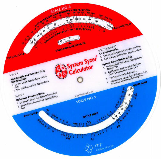
System Syzer Scale #1
The original wheel made of cardboard was 17 ½” in diameter. It is located at Bell & Gossett’s Little Red School House in Morton Grove, IL behind a glass enclosure. Nowadays, the wheel is made of plastic, measures 8″ in diameter and comes with five scales.
The first scale describes the relationship that exists between flow rate in GPM, British thermal unit (BTU) load and temperature difference. If you know two out of the three pieces of information, the wheel can give you the third piece of information instantly. For instance, if you know the BTU load and the desired temperature drop, by looking at the small window on Scale #1, the necessary flow rate in GPM is selected with a small arrow pointing at it. Scale #1 is very useful because it helps you establish GPM (the required flow rate) easily. Conversely, if you are out in the field on a problem job, by knowing the system’s flow rate and the temperature drop of the water, you can establish the actual BTU load that the system is seeing at that time.
I often explain to heating professionals how they can select smaller flow rates (GPM) by simply increasing the system’s allowable temperature drop. Traditionally, in this industry, we design around a magical number of 20°F temperature drop. By simply increasing this temperature drop to 40°F, you will have successfully cut your required flow rate in half. It’s all right there on Scale #1!
Scale #2
Scale #2 is used to select the proper sized pipe to handle your GPM flow rate. The scale lists two types of pipe: type L copper and schedule 40 iron pipe. From Scale #1 you established the required flow rate; Scale #2 allows you to select the right size pipe to support your flow rate. No more guessing! The scale lists pipe sizes from 3/8″–12″ and gives the friction loss in feet of head per 100′ as well as in millinches. Scale #2 can also be very helpful when trying to select a new pump in a boiler room. If all of the tags from the boiler and original pump are missing, you can use the existing main hot water pipe as a guide. Based upon its size, you can look on Scale #2 and determine the maximum flow that particular pipe can handle. It at least gives you a basis from which to build your theory.
Scale #3
Scale #3 confirms the proper pipe selection from Scale #2 by checking the velocity of the water. It might seem subtle, but there is a difference between friction loss in head energy versus the velocity in feet per second of the water moving through a given pipe size. Scale #3 makes sure that the selected pipe will not be noisy due to the water moving too fast. The last thing a homeowner wants to hear when the thermostat calls for heat is a whistling noise as the water screams through the baseboard piping. Whenever I select a certain size pipe to handle the GPM, I always glance down at Scale #3 just to make sure it falls within industry standards.
Scale #4
Scale #4 is like a calculator. It will tell you what the Total Pressure Drop is for a particular loop, zone or even the total system. For example, from Scale #2, you selected a certain size pipe and the scale listed out the unit pressure drop per 100′ of piping. When using Scale #4, you plug in this unit pressure drop per 100′ against the total length of piping and read the total pressure drop in the small window. Therefore, if I selected a pipe that offered 4′ of pressure for every 100′ of pipe and the total run of piping was 500′, then the total pressure drop would be 20′. This helpful information is needed when selecting a circulator.
Scale #5
Scale #5 is the most useful and yet can be the most confusing. It is based upon the fact that the friction loss described as feet of head in a hydronic system will vary approximately as the square of the change in flow rate. Scale #5 is set up to perform three functions: figure unknown pressure drops, establish system curves and select control valves based upon their Cv ratings.
When circulators are sold, sometimes they are selected by what is known as the “inventory method”…it’s the only one available! When this happens, the circulator may be a little too big or a little too small. By using Scale #5, you can build a system curve right on the pump curve chart, determining exactly where this “inventory” circulator will operate. Obviously, if the circulator is a bit too big, it will be pumping more GPM than required, which might not be a big deal as long as the increased flow rate does not exceed the pipe’s maximum velocity. If the circulator is a little too small, it will be pumping fewer GPM than required, which isn’t necessarily a bad thing, as long as the increased temperature drop does not reduce the output of the radiation. In my “Hydronic System Design” seminars, we go over these examples in great detail. Students are amazed when they finally “see” what’s going on inside those hydronic systems.
Scale #5 can be used to select control valves based upon their Cv ratings. Every valve manufacturer tests its valves to establish a Cv rating. Cv is a valve coefficient that states the necessary amount of flow (in gallons per minute) that must flow through the valve’s seat opening to cause a one-pound pressure drop across the valve. For example, a residential ¾” zone valve has a Cv rating of 3.5. This means when a flow rate of 3.5 GPM of water passes through the valve, the valve will cause a one-pound pressure drop. It will “eat up” one pound of energy head.
Another way of expressing one pound of pressure drop is 2.31′ of head loss. So if the zone valve has a Cv rating of 3.5 and you pump 3.5 GPM through the valve, the valve itself will create 2.3′ of head loss. This information is important when sizing a circulator, because in addition to calculating the pipe and radiation head losses, you have to account for the control valve’s pressure drop.
Also, by knowing a valve or any component’s flow/head rating, you can calculate the actual flow in the system by the simple use of pressure gauges. By reading the pressure before and after a pressure gauge, converting this pressure differential reading into feet of head and applying this head loss to the pump curve, you can determine the actual flow rate in the system.
Bell & Gossett’s System Syzer is a very useful tool for anyone involved the hydronic heating business. If you have any questions or comments, e-mail me at gcarey@fiainc.com, call me at (800) 423-7187 or follow me on Twitter at @Ask_Gcarey. ICM
Float and thermostatic traps (or F&T) handle condensate, air and steam differently than other traps. The thermostatic element is like the element found in radiator traps. It is normally open and its function is to pass air and other non-condensable gases into the return line. Once steam arrives at the trap, this element snaps shut, preventing steam from passing into the return lines and its job is finished until the next cycle. The float part of the trap now takes over and drains condensate as it forms. The float is attached by a lever to a plug that sits against the discharge orifice. It is normally in a closed position, until the condensate starts to arrive. Naturally, the temperature of the condensate makes no difference to the float, so as soon as the condensate enters the trap body, the float lifts the plug from its seat and starts to drain. It handles light and heavy loads very well by having the float modulate as the load changes.
Fast air removal
An F&T trap is great for handling large volumes of air and, because of this, it is very beneficial for the quick distribution of steam. Air is such a good insulator that it can greatly reduce the rate of heat transfer to heating equipment and slow down the distribution of steam throughout a system. Applications such as the end-of-main drips, unit heaters, heat exchangers, make-up air coils and anything else that requires air to be removed quickly are perfect for this trap.
Checking F&T traps
Because the trap discharges condensate at saturation temperature, it can be misleading to use the temperature coming out of the trap to check proper operation. Also, because the condensate will be at saturation temperature, a percentage of the condensate discharging from the trap will flash back into steam. Therefore, the best method for checking good traps is visual inspection of the discharge coming from the trap. However, don’t be fooled by the flash steam that may discharge from the trap. A good trap will discharge water with a small percentage of flash steam while a bad trap will have virtually no water while it passes steam with a noticeable hissing noise and plumes of white clouds. Most modern F&T traps come with four ports, two inlets and two outlets. Instead of plugging the second outlet, create a test station by installing a short nipple, service valve and a cap. Then when you want to check the trap, simply take off the cap, open the service valve and monitor its discharge.
Trap Sizing
The sizing of F&T traps is very important for proper operation and longevity of the trap. Many times these traps are line-sized, that is, the size of the steam pipe becomes the size of the trap. The problem with this method of “trap sizing” is the steam pipe is sized to handle steam while the trap is intended to handle only air and condensate, not steam. Remember, low pressure steam expands approximately 1,700 times the volume that a comparable amount of water requires. That is why the steam mains are so big. The best way to make sure a trap will be applied properly is to calculate the actual condensate load the trap is going to handle, apply the proper safety factor and select the lowest pressure differential that will occur across the trap. This is important because if you select a trap that can handle the condensate load, but at a greater pressure differential than it will actually encounter, the condensate won’t drain from the trap. Instead it will back up into the coil or heat exchanger causing water hammer, reduced output and possible damage to the heating unit.
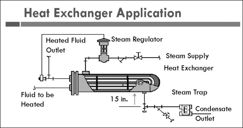
An example would be selecting an F&T trap for a steam-to-water heat exchanger. If the heat exchanger has a control valve on the steam supply line, when the valve closes there will be no steam pressure on the inlet side of the F&T trap. The only pressure differential that exists will be the vertical distance from the bottom of the heat exchanger to the inlet of the trap. Ideally the trap should be at least 15″ below the heat exchanger, which will give you a 0.5 lb pressure differential. Select a trap that can pass the condensate load (with the proper safety factor) at the 0.5 lb pressure differential and you will be assured of complete condensate drainage every time.
If you have any questions or comments, e-mail me at gcarey@fiaince.com or call me at FIA. 1-800-423-7187 or follow me on Twitter at @Ask_Gcarey. ICM
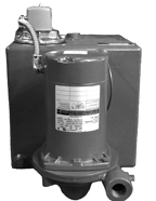
Understanding the operation of a condensate pump is pretty straightforward. The condensate pump is made up of a pump and motor with an impeller on the end of it, a receiver that the pump and motor is mounted on (usually cast iron but also steel can be used). Cast iron receivers are more rugged and last longer in these corrosive environments. Condensate usually has a low pH (which means it is on the acid side).
Inside the receiver is a float assembly (not unlike a ballcock found in a toilet) that is connected to a float-operated electrical switch, which is attached to the receiver. The receiver has an inlet opening near the top side of the receiver; it also has an opening on the top where a vent pipe is connected. The condensate return piping from the system is connected to the inlet connection of the receiver. The vent pipe is used to vent the air from the system. As condensate and air travel along the return piping, it enters into the receiver through the inlet connection. The condensate then falls to the bottom of the receiver while the air enters into the receiver and exits out through the vent pipe located at the top of the receiver.
In effect, the vent pipe of the condensate pump is the main air vent for the system. Make sure that there are no water pockets in the return piping because that could prevent air from getting out of the system. Also never plug the vent line because condensate pumps are not rated for pressure. If they become “pressurized” because of a blocked vent line, they could explode!
As the condensate continues to gather in the receiver, the float part of the assembly starts to “float” up or rise up with the rising level of condensate. At some point, the float-operated electrical switch “makes,” closing a set of contacts that turn the pump on. The condensate pump discharges the condensate to either the boiler directly or maybe to a boiler feed tank in the boiler room.
Naturally, as the pump discharges the condensate from the receiver, the water level and the float in the receiver lowers to a point where the switch “breaks,” opening the contacts that turn the condensate pump off. That is basically what a condensate pump does—as returning condensate enters the receiver, it raises the float, which eventually turns the pump on. As the water level drops in the receiver, so does the float, eventually turning the pump off.
The Devil is in the Details
There are a couple of details that you need to pay attention to when piping a condensate pump into the system. On the inlet side of the receiver, it is good piping practice to install some type of strainer (Y strainer or basket strainer are two popular choices) just before the condensate enters into the receiver. There is sediment in old steam systems that the condensate will pick up as it is flowing back to the receiver. If the sediment makes its way onto the face of the pump’s seal, it will groove lines into the carbon and ceramic seal causing it to leak. If the leak isn’t discovered quickly, the condensate will work its way into the bearings of the motor, causing it to eventually fail.
On the discharge side of the pump, there should be a check valve, a balancing valve and a service valve. The purpose of the service valve is that if you need to work on the pump, you can close the service valve and isolate the pump from the system. The check valve is needed so whenever the pump is off, the water that is in the piping on the discharge side of the pump doesn’t fall back into the receiver. If the check wasn’t there, or if sediment gets underneath the flapper of the check, the water would flow back into the receiver causing the float to rise and bring the pump on. The pump would then unload the receiver and shut off. This cycle would “seesaw” back and forth endlessly.
If you happen to walk into a boiler room in the summertime and the steam boiler is off because it is used for heating, but the condensate pump turns on and off again and again, the check valve has most likely been compromised. Dirt or sediment is probably keeping the flapper from seating properly on its seat. The balancing valve is used to provide a certain amount of “back pressure” on the pump.
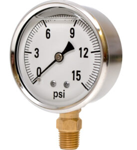
Standard stocked condensate pumps are rated to pump the condensate at a discharge pressure of 20 psig. But in most applications the boilers are running at very low pressure, typically 2–5 psig. When the pump turns on and it doesn’t “see” 20 psig of pressure, it will run way out on its curve, pumping too much condensate too quickly. It can cause the check valve to chatter, creating unnecessary noise. By closing the balancing valve, you are creating the additional pressure the pump was designed to work against, thus slowing the flow rate down to where it can operate properly and quietly.
Condensate Temperature
I get calls every now and then complaining about the condensate pump turning on, but not pumping water out of the receiver. In some cases, the water starts pouring out of the vent pipe. Usually the problem is related to the temperature of the condensate. I am not referring to temperature that exceeds the material of construction or the pump’s seal rating (most are rated at 250°F). What I am referring to is when steam is allowed to enter into the return lines (usually bad traps that have failed in the open position) and elevate the returning condensate’s temperature above 185–190°F.
When the condensate becomes too hot and gets close to its boiling point, there isn’t enough pressure on the water to remain a liquid. When the pump turns on and the water enters into the eye of the impeller, it experiences a drop in pressure. Because the water is so close to its vapor pressure (boiling point), it flashes into vapor/steam. Of course, the impeller isn’t capable of pumping steam, so the impeller is spinning at 3,600 rpms and no water is discharging out of the receiver. This isn’t because of a bad pump, the water is simply too hot. There isn’t enough pressure on the water to keep it in its liquid state.
Remember, this is an open system and the only available pressure is the height of the condensate that is sitting in the receiver, which is less than a foot. In a closed hot water heating system, you have a fill valve and an expansion tank that provides a lot of pressure so the pumps have no problem circulating the 200°F water.
The answer to this problem is to lower the temperature of the condensate. Fix the radiator traps that are leaking and make sure the pressuretrol isn’t set too high. There is a relationship between the pressure of the steam and its corresponding temperature that holds true to the temperature of the condensate. This is another reason why there is no benefit to cranking up the pressuretrol setting in a heating application. ICM
If you have any questions or comments, e-mail me at gcarey@fiainc.com; call me at FIA 1-800-423-7187 or follow me on Twitter at @Ask_Gcarey.
There was a man named Gil Carlson who worked at Bell & Gossett. He eventually became known as the “Father of Modern Hydronics.” He invented products and developed various theories and applications that today we consider standard procedures. His most important discovery was the “Point of No Pressure Change.” This subject deals with the importance of proper pump location in a closed hydronic system.
A gauge would register one pound per inch if you placed it at the bottom of a column of water 28 inches high.
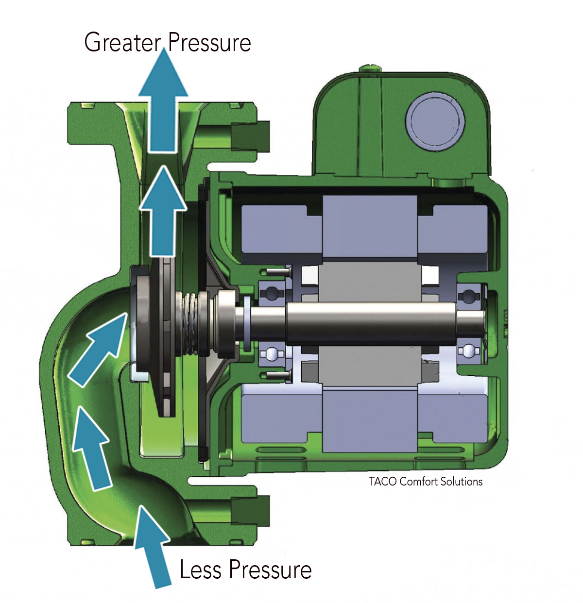
The direction water flows is determined by the higher pressure
found on the discharge side of the circulator.

According to Boyle’s Law, if a gas is squeezed, its pressure will rise; if a gas is expanded, its pressure will drop.
Hydronic systems are filled with water and any air in the piping system rises to the high points. This air must then be vented out of the system. If the air is allowed to gather at these high points, it can prevent the circulation of water. A typical circulator pump can not push the air down a vertical pipe, since air is lighter than water. Only positive displacement by means of opening a drain and pushing the air down the pipe with more water (purging) will remove the air pocket.

Once you have vented the high points of the system, circulation can take place. However, air problems can still occur. We must provide some means for preventing air from getting back into the piping system. This is because water “holds” a percentage of air in solution. As the temperature of the water increases, the amount of air held in solution decreases and is released in the form of air bubbles.
In a hot water system, large quantities of air are released in the boiler when the water is heated. The air bubbles will travel out into the system and find low velocity areas where they will collect, causing air binding and no circulation. This will require the venting of these air pockets again! When this air is vented, the systems pressure drops, causing the fill valve to respond, bringing in more water. This sets up a never-ending cycle that not only is a nuisance but is also very corrosive to the system components.
Full of Hot Air
It is obvious from the above information that we must do something with the air as soon as it is released from solution (i.e., when the boiler heats the water). The logical place for this to occur is right at the outlet of the boiler. The question is: Do we vent these air bubbles out to the atmosphere or do we direct them up into a plain steel compression tank? The answer to this question has been argued and debated over the years. Venting the air to the atmosphere and using a diaphragm expansion tank is the most popular method and with good success. The important thing is to know how to install or replace either method properly.
The air control system came from the old gravity hot water systems that used an open expansion tank located in the attic. As water is heated, it expands in volume. By installing this tank, technicians provided a place for this expanded water to go so that the pressure did not build to the point of causing the relief valve to open. They normally piped this tank off the supply main up to the attic. Because the flow rate was so slow in a gravity system, the air had no problem finding its way up to this open tank. However, when the systems were being changed over to forced circulation, they started to experience air-binding problems. This was caused by the “booster” pumps. The water was moving at a flow rate that was too fast to allow the air bubbles to make a sharp turn and go up the pipe leading to the open tank in the attic.
Catching Bubbles
The engineers at the time realized they had to control the air as soon as it was released from the boiler. They came up with various devices designed to “catch” the air bubbles and direct them towards the expansion tank. This brings up an important point. The air bubbles move through the piping towards the tank by gravity. This means the piping must be pitched up towards the tank, which has to be located above the boiler. That is why you will see these tanks suspended from the ceilings in the boiler room.
Automatic air vents should not be used with this type of system. They defeat the purpose of what you are trying to accomplish—control the air but do not vent it. Every time air is vented from the system, it is lost from the expansion tank. This venting action also lowers the system’s pressure. Of course, an automatic water feeder opens in response to this drop, bringing in fresh make-up water that enters the expansion tank. This raises the water level in the tank and after a few cycles there is no more space left for expansion. The relief valve will then discharge water every time the boiler fires up.
The only type of vent you can use is a manual one, which can be opened to vent air on initial filling of the system. The purpose behind air control was to use the body of air as a spring to maintain pressure on the system as well as accept the expanding water that happens when the boiler heats the water. If you lose the body of air through automatic vents or leaks, etc., it will be replaced by water. Since water is not compressible, when it is heated and expands the pressure builds. When the relief valve discharges, the system pressure drops and more make-up water is added. This water contains a lot of oxygen, which is very aggressive and attacks the ferrous metals in the system.
Air Elimination
The other system is called air elimination. This means venting air out of the system using automatic vents and using a diaphragm expansion tank. This expansion tank has some type of rubber membrane that separates the system water from the air. The tank comes pre-charged from the factory with 12 psig of air charge. Because the air is separated from the system water, you are no longer concerned with directing air bubbles out of the boiler and up into the expansion tank. This gives you the flexibility of installing the diaphragm tank anywhere. It can be installed on the floor, suspended from the bottom of an air separator or even suspended from the ceiling. The size of the tank is generally smaller than the steel expansion tank because there is no water in the tank until the system water is heated.
An important point that is often overlooked is the pre-charge of the tank. It should match the system’s required fill pressure. If a tank is installed into a system where the fill pressure is greater than the factory pre-charge (12 psig), you should increase the air charge to match the fill pressure setting. If you do not (and a lot of people don’t), water will enter the tank once the fill pressure exceeds the air charge in the tank. The problem is the tank becomes undersized and allows the system pressure to exceed the setting of the relief valve.
In these examples, the tank gets blamed for being defective when all it needs is an increase in its air charge to match the fill pressure. The most common device used to help eliminate the air is an air scoop. This separator slows the velocity of the water flow, allowing the air bubbles to separate from the pumped flow. On the top of this “scoop” is an automatic vent that releases the air out of the system. It is important that the air separator be installed correctly.
Whether you are working on an older steel compression tank style system or installing a new residential hydronic heating system with a diaphragm expansion tank, it is important that you “handle” the air properly in both systems to avoid callbacks and customer complaints. ICM
If you have any questions or comments please call me at 1-800-423-7187 or email me at gcarey@fianince.com. Twitter: @Ask_Gcarey
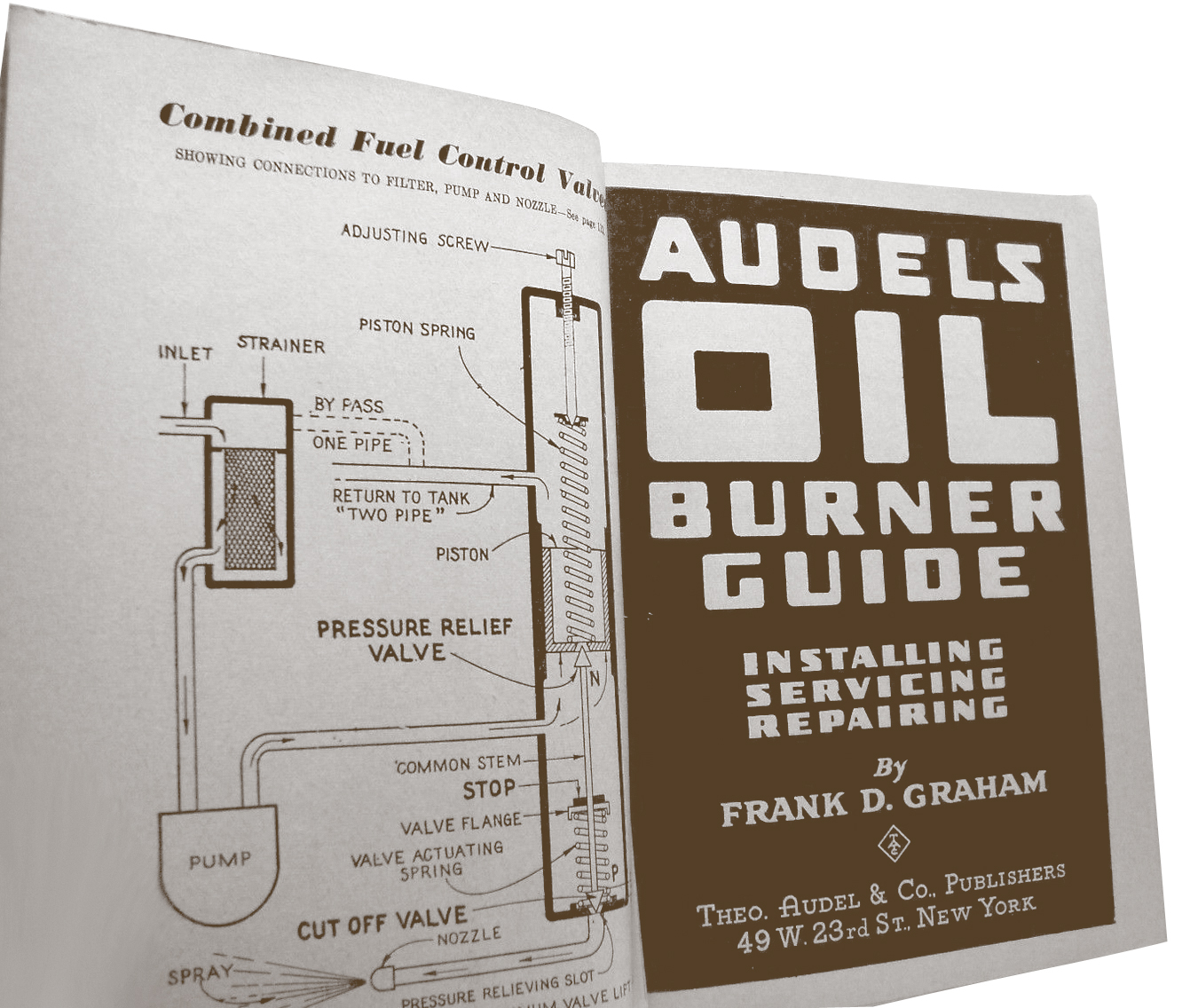
Over this past winter, I was called on to look at a one-pipe steam system. The homeowner was complaining that his steam system was operating inconsistently since the new boiler was installed. The primary complaint was that certain radiators just wouldn’t heat while others were heating fine. The only way he could get the “cold” radiators hot was to turn the thermostat way up. Naturally, the rooms with the “good” radiators became hotter than a steam room. As we walked through the house, we checked out all the radiators and their vents and then into the basement to find the main vents. As I was doing this, I couldn’t help but remember the name of a book, Audels Oil Burner Guide, which was published in 1946. In the book, there was a chapter dedicated to the subject of converting a coal-fired, one-pipe steam system over to oil. The chapter stressed how much more important it was to vent the air from the system when it was converted to oil than when it was coal fired.
The book reasoned that once a steam boiler was fired with coal, the source of steam was constant. There was a consistent “push” of steam slowly nudging all the air out of the system through whatever venting was available. Once converted to oil, however, the source of steam was controlled by a thermostat turning the burner on and off. There was no longer this constant source of pressure in the system pushing the air out through the vents. Instead, the pressure was intermittent. As long as the thermostat was calling for heat, the burner would produce steam and air was vented from the system. Once it was satisfied, the burner was shut off. This left portions of the house cold because all the air hadn’t been vented from either the system main and/or the individual radiators before the thermostat was satisfied.
Audels explained that, because the vents used were non-adjustable, the radiators close to boiler would heat quicker than the ones further away. That is because the steam had to remove the air from the piping before it reached the furthest radiators.
Adjustable vents
The way to prevent this from happening, the book said, was to install adjustable vents on all the radiators. By adjusting the radiators close to the boiler to a slower venting rate and increasing the venting rate of the further radiators, you could synchronize the heating of all the radiators. You could balance the system by having the steam enter all the radiators at the same time.
The book cautioned against taking this adjustable venting to an extreme. In systems where all the radiators are the same size, and you have to adjust the venting rates solely because of the radiators’ location, the amount of throttling isn’t excessive and won’t hold back the heat.
On jobs where smaller radiators are mixed with considerably larger, slow-to-heat radiators, the application of adjustable vents is different. When the same size air vents are installed on radiators varying in size, it will obviously take longer for the larger radiators to remove the air than the smaller radiators. This means you have to throttle back considerably on the smaller radiators while the air is venting from the larger, slow-to-heat radiators.
Guess what you are throttling back? The heat. This is what the book meant by misapplying the principle of adjustable venting. Instead of cranking down the venting rate of the smaller radiators, why not increase the venting rate of the hard-to-heat radiators? The book recommended drilling and tapping a second 1/8-inch hole in the radiator and installing a second vent. That way, instead of having to throttle back excessively on the smaller radiators, you have provided a second hole to remove the air quickly in the oversized radiators. By opening the venting rate of the smaller radiators, you have provided two benefits:
Venting the mains
The venting of a steam main became more important when the boiler was converted from coal to oil. The book advised that you install at least one ¾-inch main vent at the end of every main. There is a huge amount of air in these pipes. If you rely on the radiator vents to remove this air, you will definitely experience unbalanced heating.
Think about it for a minute. Radiator vents, as the name implies, are designed to vent air from radiators. Not from 2″, 3″ or 4″ steam mains. Main vents are much bigger with greater venting rates than radiator vents. The book explained that by installing main vents at the end of each main, steam would be distributed throughout the house quickly. That is exactly what is needed. Faster distribution makes sure the steam reaches all the radiators before the thermostat shuts off the boiler. If the system had more than one main and the mains were not the same length, the book suggested that two or more ¾” vents are installed on the longer main and one vent on the shorter main. This would create a balance of steam traveling through the whole system at about the same time.
Lessons from the past
This information must have been valuable for the servicemen working on steam systems in the days when coal systems were being converted to oil. It occurs to me, however, that a high percentage of the steam heating systems we work on today started out as coal-fired boilers. And what is the biggest complaint from homeowners who live with one-pipe steam systems? Maybe if we applied some of the tips from Audels Oil Burner Guide and vented the system as described, those complaints would disappear.
I think a replacement boiler installed today is essentially a conversion job. The new boiler is very different from the old boiler. It makes steam much faster because it doesn’t hold nearly as much water as the old boiler. Consequently, it will build pressure faster if the air in the system isn’t vented fast enough. Before you know it, the new boiler is cycling on and off the pressuretrol and the customer is complaining that his old boiler never did that!
Don’t turn the pressuretrol up figuring that will stop the short cycling. The higher pressure only burns more fuel, keeps all the radiator vents closed because the higher pressure exceeds the drop-away ratings of the vents and creates system imbalances. Instead, the answer to this common problem is to vent the mains aggressively and use some tricks from the old-timers who wrestled with these systems years ago.
If you have any questions or comments, e-mail me at gcarey@fiainc.com; Tel: 800-423-7187 or follow me on Twitter at @Ask_Gcarey. ICM
The heating industry, for the past decade, has focused on improving the combustion or thermal efficiencies of the boiler. Every major boiler manufacturer has a series of modulating/condensing boilers in its product offering. The number of mod/con boiler installations has been growing every year and is expected to continue to grow. Some of the boilers, when installed in the right application, are achieving efficiencies in the 95% + range. People in our industry are under the impression that with thermal efficiencies this high, there isn’t any room left for improving a hydronic heating system. Their thinking would be correct if combustion efficiency was the only goal. However, there is another efficiency that the industry had ignored for years but is starting to look at and that’s the hydraulic efficiency of the distribution system. We should be looking at overall system efficiency which includes how efficient the boiler plant converts fuel into heated system water and how efficiently this heated water is delivered to the building?
First, let’s define what distribution efficiency is:
EFFICIENCY
Desired OUTPUT quantity/ necessary
INPUT quantity.
In basic terms, how much energy is needed to get the desired output? When we apply the definition of distribution efficiency to a heating system, it looks like this:
DISTRIBUTION EFFICIENCY
rate of heat delivery/ rate of energy use by
distribution equipment.
If a heating system provides 120,000 BTU/H at outdoor design conditions and they have four circulators that consume 90 watts each, the distribution efficiency for that system is:
DISTRIBUTION EFFICIENCY
120,000 Btu/h/ 360 watts
= 333Btu/h / watt
Compare that to a warm air furnace where the blower motor consumes 1,050 watts while delivering 110,000 Btu/h through the duct system. The distribution efficiency for that system would be:
DISTRIBUTION EFFICIENCY
110,000 Btu/h / 1050 watts
= 105 Btu/h / watt
The hydronic system has a higher distribution efficiency than the warm air furnace because the physical properties of water are much better for conveying heat than air.
Even though hydronic systems generally have a higher Distribution Efficiency than air systems, when the number of pumped zones increases, the distribution efficiency can quickly dissolve. For example, I recently visited one of those “McMansions” where they had 34 zones, all with water lubricated circulators consuming 90 watts each. The house had a design load of 350,000 Btu/hr. When you run the numbers to determine the distribution efficiency:
DISTRIBUTION EFFICIENCY
350,000 Btu/hr / 34 x (90 watts)
= 114 Btu/hr / watt
As you can see, a hydronic system, when taken to the extreme, can become an inefficient distribution system. These systems have been installed for years with no real concern for operating costs. However, as energy costs continue to rise, not only has it impacted both fuel costs for transportation and heating homes, but also electrical costs. Power plants that produce electricity have to use some source of energy. The majority has used coal for years, but through legislation many plants are being closed down or converted to natural gas. This is putting tremendous pressure on the ability for the power plants to manufacture electricity. The result? Higher electric bills! In Europe, where they have experienced higher fuel and electric costs, they were forced to come up with better and more efficient ways to heat the water and deliver the heated water to the heating terminal units. One of the technologies they have embraced for the past 15 years is electronically commutated magnetic motors, known as ECM. The majority of residential homes in Europe use hot water heating to warm their homes. To achieve higher distribution efficiencies they have incorporated ECM technology into their circulators. In fact, nowadays only ECM circulators are allowed to be installed in Europe. The pump manufacturers their have combined their efforts to improve the efficiency of the circulators they offer for hot water heating systems. They came up with an efficiency index that the all of the pump manufacturers had to reach: Energy Efficiency Index (EEI). The European Community recently created legislation to adopt EEI. While trying to reach these efficiency standards, the manufacturers quickly realized they could not achieve the necessary efficiency points with induction motor technology. It just proved to be too inefficient so they moved to ECM motor technology.
Utilities in the U.S. Northeast are providing rebate incentives for residential ECM circulators. It seems they are very interested in having the hydronic industry move away from the old, inefficient induction motors and move towards ECM technology. Plumbing and heating wholesale distributors sign up and become part of the Utility’s high-performance circulator program. They then can offer a $100 discount off the price of any of the participating ECM residential circulators. Why would they provide such a generous incentive? It has to do with energy costs and energy consumption. As energy costs continue to rise, the impact affects everyone. Production costs go up, distribution costs go up and the net result is higher utility bills for the end user.
If we were to re-examine our Distribution Efficiency formula while incorporating the new ECM circulators that can consume considerably less watts, the distribution efficiency can be markedly improved. If we go back to that McMansion that had 34 water lubricated zone pumps and replaced them with the ECM pumps with speed control (that allows the pump to be set for the zone’s actual load), the formula would look something like this:
DISTRIBUTION EFFICIENCY
350,000 Btu/hr / 34 x (20 watts)
= 515 Btu/hr / watt
If you have any questions or comments, e-mail gcarey@fiainc.com, call 1-800-423-7187 or follow me on Twitter at @Ask_Gcarey ICM
With focus on high efficiency and “greening” the heating industry, low temperature system designs and applying outdoor reset controls to every hydronic system, steam systems are being viewed as highly inefficient. The current approaches described are all good ones, of course, but they’ve resulted in the notion that steam systems must be converted to hydronic systems instead. Naturally, if it’s an option, then converting to a forced hot water system has benefits. Unfortunately, the possibility isn’t always available. That being the case, there are steps you can use to greatly improve the operation and reduce its consumption of energy.
Size the boiler correctly
It is essential to make sure your boiler is sized properly so that when the thermostat calls for heat, the boiler can produce enough steam to fill all the radiators and associated piping. When boilers are too big, they cause short-cycling, which hurts the boiler’s efficiency. Conversely, if the boiler is too small, when the thermostat calls, the boiler will run forever without building any pressure, heating only a portion of the building. This is a tremendous waste of energy, expensive and not very “green.”
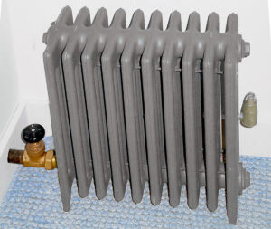
How do you provide a properly sized steam boiler? You need to count the connected load. This means you have to walk throughout the home or building and calculate each radiator’s square foot rating. Then you add up the total load in square feet and select the boiler that has the closest capacity to your connected load. This is the most effective way of making sure the boiler will meet your system’s needs.
Make sure to insulate the mains
Steam is water that has enough heat added to change it to a gas state. This gas desperately wants to change back into water and it does so every time it comes in contact with something cooler that itself. Old-timers insulated the mains so that the steam the boiler produced ended up in radiators where people live, not condensing in piping downstairs. They knew that a bare steel pipe experienced heat loss five times greater than an insulated pipe.
Unfortunately, the material of choice back then was asbestos. We all know now that might not have been the best choice, but in fairness it was all they had at the time. When that asbestos insulation gets removed, you really should replace it, otherwise the boiler may become undersized, creating very warm basements with cold and unhappy people upstairs as well as higher fuel bills.
Can air get out?
Steam and air are both gases but with different densities. When the system is off, all piping and radiation above the water line is filled with air. Once the boiler starts making steam, it wants to escape the system. If the air can’t get out quickly and easily, the steam will start to build pressure back in the boiler. The pressuretrol will respond to this by shutting the burner off. Of course, the steam didn’t get very far into the system and what did quickly condenses, dropping the pressure.
Before you can say “short-cycling,” the burner is back on, steam heads out into the system, bumps up against the air, pushes, pressure increases and the burner is off again. This represents a considerable waste in fuel consumption and a very uncomfortable heating system upstairs. Resist the urge to turn the pressuretrol up to stop the short-cycling, because the issue is air! If you have a one pipe system, make sure all the radiator vents are working properly.
Over the years, rust flakes and other debris can get picked up with the steam to become lodged in the vent’s port opening. This will decrease venting capacity or worse, not allow the vent to close in the presence of steam. While you are wandering through the system, check to make sure the mains are properly vented with main steam vents. By venting the mains with large capacity vents, steam will be able to travel to the ends of the main very quickly. This greatly improves the distribution of steam throughout the building. The result is heat moves from the boiler room to the people upstairs faster, satisfying the thermostat and turning the burner off. This saves fuel consumption, lowers your heating bill and reduces your carbon “footprint”.
If you are working with a two pipe system, instead of vents on the radiators, you will have to contend with steam traps. Even though they look very different, a steam trap has the same responsibility to remove air from the radiator so steam can get in. A steam trap is basically a thermostatic valve that opens and closes in response to changes in temperature. During the course of a normal heating season, a trap will cycle open and close approximately 150,000 times! Every year, after so many heating seasons, component fatigue alone damages these traps. Never mind water hammer, aggressive condensate, etc. So when they finally do give up their ghosts, usually steam traps will fail in one of two manners: closed or open. If the trap fails closed, no air can get out and therefore no steam can get in. The result is a cold radiator. If the trap (or more likely traps) fails to open, now steam is allowed to pass through the radiator and into the return piping. At this point, all hell breaks loose! Once steam makes its way into the returns, the system starts to lose its pressure differential—meaning the pressure in the return lines starts to equal the pressure in the supply mains. The steam stops dead in its tracks, because without a pressure differential there is no motive force; there is no high going to low. It’s all the same pressure. The system heats poorly at best, the burner runs forever trying to satisfy the call for heat, fuel consumption is through the roof and the heating bills are excessive. There is no getting around it, traps have to be maintained.
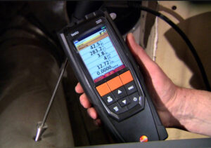
Keep an eye on the system’s pH
This is a little tidbit that Dan Holohan told me about—knowing the pH level in a steam system can help prevent or solve problems where the solution isn’t all that obvious. When a boiler produces steam, one of the by-products released along with it is carbon dioxide. That happens because boiler water make-up contains carbonates and bicarbonates, which break down while the boiler makes steam. This carbon dioxide travels with steam out into the system. If it is not vented right away, it will dissolve into the condensate that is formed when steam condenses. This results in the formation of carbonic acid, which is a very corrosive substance. It will slowly “munch” away at the piping and fittings. To make matters worse, oxygen (air) mixes in with the carbonic acid to form rust (ferric hydroxide). Typically, if you were to take a pH reading on your average steam system, it would be on the lower acid side of the scale.
Some guys are into using boiler chemical cleaning agents to “clean” the boiler after a new install or after some maintenance work was done on the system. Sometimes too much of a good thing can be bad. If the pH level becomes too high, the water is no longer acidic (that’s good) but a high alkaline level will cause the boiler to foam when it makes steam, and this foaming creates heating problems. When the steam exits from a boiler that is foaming, it will carry some of the foam with it. Unfortunately, the water in the foam robs the steam of its latent heat before it gets out to the radiators. The boiler makes lousy steam, it runs forever trying to satisfy the thermostat, the heating bills become excessive and the homeowner is not happy. Carry with you some pH papers so you can check out the pH level of that next trouble steam job. Ideally, try to keep the level somewhere between seven (which is neutral) and nine (slightly on the alkaline side).
By applying some of these strategies you will be reducing that steam boiler’s carbon “foot print” and, more importantly, keeping your customer warm and happy. ICM
If you have any questions or comments, e-mail gcarey@fiainc.com, call me at (800) 423-7187 or follow me on Twitter at @Ask_Gcarey.
During the past few months, we have been presenting quite a few seminars on various heating subjects. One of the subjects was Troubleshooting Steam Systems, which concentrates on understanding and troubleshooting the different types of steam heating systems. Of all the systems we discuss, one-pipe systems are perceived as being the easiest to understand. The reasoning is very logical: there is only one pipe feeding each radiator, what’s so difficult to understand? However, as we got into the “hidden” aspects of one-pipe systems, the contractors started realizing these systems have certain rules that need to be followed if the system is going to be successful. A typical one-pipe steam system chugs along for years unnoticeably, until finally the boiler needs to be replaced or the new homeowner decides to remodel a kitchen or bedroom and needs to move or relocate some radiation. If it is done correctly, the system will continue to provide warmth to the house but as soon as one of the “rules” is ignored, anything can happen.
This is what was happening with a newly renovated house with an old steam system. They were experiencing cold radiators and spitting vents and a friend of mine asked me to take a look. One of the first things I check when troubleshooting a steam system that has a brand new boiler is to make sure the boiler was sized for the connected load. This means counting the square foot equivalence of direct radiation (EDR) rating of all the radiators in the house to see if it matches the boiler’s rating plate. This is important for two reasons:
1. If the boiler rating is less than the connected load, it won’t be able to heat all of the radiators in the house because it is undersized.
2. If the boiler rating is greater than the connected load, the system will experience velocity and counter-flow problems. This can lead to spitting radiator vents, sloshing, gurgling and banging pipes and radiators, boiler short-cycling and uneven heating.
It turns out the boiler was considerably oversized, which created a lot of problems. Making matters worse, during the kitchen remodel, they moved a couple of radiators to the other side of the room. This seemed innocent enough. Unfortunately, there exists another rule governing the size, the pitch and the length of pipe run used to feed each radiator and this is critical, especially in one-pipe systems. The reason is basic; the pipe that is used to deliver steam out to the radiator also brings the condensate formed in the radiator back to the main. This occurs simultaneously so it is important the velocity of the steam (how fast it is traveling towards the radiator) doesn’t exceed a maximum. If it does, the condensate won’t drain back and in fact will be driven towards the radiator, causing banging and sloshing noises. Think of it this way—steam traveling in a pipe is like wind heading in one direction, while the condensate is trying to gravity drain back underneath this wind in the opposite direction. So long as the tunnel is big enough and there is sufficient pitch, things will work as they should.
When our contractor friends remodeled the kitchen, they were not aware of these piping concerns. They used the same size pipe that had worked for the last 60 years, but with the oversized boiler and the additional length of horizontal run from the main to the radiators, they had nothing but cold, noisy cast iron decorations.
Another time, a contractor asked me to visit an apartment building that was giving the property management company a lot of headaches with nuisance service calls. What we saw when we walked into the boiler room was quite remarkable. The first thing that got my attention was the six old pressure reducing valves (PRVs) sitting on top of the boiler. The next item of interest was the expansion tank or lack thereof; there was a ¾” copper line piped off the top of the boiler and it went straight up into the sheet rocked ceiling.
However, we couldn’t see any expansion tank, only a piece of pipe! The final piece was the piping of the relief valve. Connected to the bottom of the discharge line from the valve was a piece of 6″ flue pipe that was positioned by a milk crate wedged against the boiler. From there, more flue pipe was attached. The janitor had built a drainage system using the flue pipe that ran from the bottom of the relief valve piping in the boiler room to a back room where a floor drain was located.
The relief valve would constantly dump water onto the floor every time the boiler fired. He was tired of mopping up the water and built the “drainage system” that emptied into a floor drain. When the boiler turned off, the pressure in the system would drop. This caused the PRV to feed gallons of make-up water back into the system. Unfortunately after a few of these cycles, the minerals from the raw make-up water came out of solution and gathered on the PRV’s seat, causing it to become plugged and then fail. Next came numerous phone calls to the management company from the upper floor tenants complaining of being too cold. Of course, where there is no water, there is no heat! To solve this problem, the janitor would then replace the “old” pressure-reducing valve with a brand new one. This continued throughout the entire heating season.
The cause of this whole miserable story was the hidden, waterlogged steel expansion tank that was concealed above the sheet rock. It appears the tank had been installed incorrectly ever since the boiler was replaced. The janitor had access to the tank and he would just drain it down every time it became waterlogged. Once the new ceiling went up and covered the tank, the problems multiplied. Instead of solving the real issue of why the tank was waterlogging in the first place, the janitor just did what he could, which was to build a “drainage system.”
Both of these problems shouldn’t have happened. The information is readily available; just take the time to ask! ICM
If you have any questions or comments, e-mail gcarey@fiainc.com, call me at (800) 423-7187 or follow me on Twitter at @Ask_Gcarey.