Hydronic systems are filled with water, so any air in the piping system rises to the high points. This air must then be vented out of the system. If the air is allowed to gather at these high points, it can prevent the circulation of water. A typical circulator pump cannot push the air down a vertical pipe, since air is lighter than water. Only positive displacement, by means of opening a drain and pushing the air down the pipe with more water (known as “purging”), will remove the air pocket.

Once you have vented the high points of the system, circulation can take place. However, air problems can still occur. We must provide some means for preventing air from getting back into the piping system. This is because water “holds” a percentage of air in solution. As the temperature of the water increases, the amount of air held in solution decreases and is released in the form of air bubbles. In a hot water system, large quantities of air are released in the boiler when the water is heated. The air bubbles will travel out into the system and find low velocity areas where they will collect, causing air binding and no circulation. This will require the venting of these air pockets again! When this air is vented, the system’s pressure drops, causing the fill valve to respond, bringing in more water. This sets up a neverending cycle that is not only a nuisance, but is also very corrosive to the system components.
It is obvious from the above information that we must do something with the air as soon as it is released from solution (i.e., when the boiler heats the water.) And the logical place for this to occur is right at the outlet of the boiler. The question is, do we direct them up into a plain steel compression tank or do we vent these air bubbles out to the atmosphere? The answer to this question has been argued and debated over the years. Venting the air to the atmosphere and using a diaphragm expansion tank is the most popular method and has met with good success. The important thing is to know how to install or replace either method properly.
The Air Control system came from the old gravity hot water systems that used an open expansion tank located in the attic. As water is heated, it expands in volume. By installing this tank, they provided a place for this expanded water to go so the pressure did not build to the point of causing the relief valve to open. They normally piped this tank off the supply main up to the attic. Because the flow rate was so slow in a gravity system, the air had no problem finding its way up to this open tank. However, when the systems were being changed over to forced circulation, they started to experience air-binding problems. This was caused by the “booster” pumps. The water was moving at a flow rate that was too fast to allow the air bubbles to make a sharp turn and go up the pipe leading to the open tank in the attic.
The engineers at the time realized they had to control the air as soon as it was released from the boiler. They came up with various devices designed to “catch” the air bubbles and direct them towards the expansion tank. This brings up an important point. The air bubbles move through the piping towards the tank by gravity. This means the piping must be pitched up towards the tank, which has to be located above the boiler. That is why you will see these tanks suspended from the ceilings in the boiler room.
Automatic air vents should not be used with this type of system. They defeat the purpose of what you are trying to accomplish; control the air but do not vent it. Every time air is vented from the system, it is lost from the expansion tank. This venting action also lowers the system’s pressure. Of course, an automatic water feeder opens in response to this 22 ICM/June 2012 drop, bringing in fresh make-up water that enters the expansion tank. This raises the water level in the tank and after a few cycles, there is no more space left for expansion. The relief valve will then discharge water every time the boiler fires up. The only type of vent you can use is the manual type, which can be opened to vent air on initial filling of the system. The purpose behind Air Control was to use the body of air as a spring to maintain pressure on the system as well as accept the expanding water that happens when the boiler heats the water. If you lose the body of air through automatic vents or leaks, etc., it will be replaced by water. And since water is not compressible, when it is heated and expands, the pressure builds. When the relief valve discharges, the system pressure drops and more make-up water is added. This water contains a lot of oxygen, which is very aggressive and attacks the ferrous metals in the system.
The other system is called Air Elimination. This means venting air out of the system using automatic vents and using a diaphragm expansion tank. This expansion tank has some type of rubber membrane that separates the system water from the air. The tank comes pre-charged from the factory with 12 psig of air charge. Because the air is separated from the system water, you are no longer concerned with directing air bubbles out of the boiler and up into the expansion tank. This gives you the flexibility of installing the diaphragm tank anywhere. It can be installed on the floor, suspended from the bottom of an air separator or even suspended from the ceiling.
The size of the tank is generally smaller than the steel expansion tank because there is no water in the tank until the system water is heated. An important point that is often overlooked is the pre-charge of the tank. It should match the system’s required fill pressure. If a tank is installed into a system where the fill pressure is greater than the factory pre-charge (12 psig), you are suppose to increase the air charge to match the fill pressure setting. If you do not (and a lot of guys don’t), water will enter the tank once the fill pressure exceeds the air charge in the tank. The problem is the tank becomes undersized and allows the system pressure to exceed the setting of the relief valve.
In these examples, the tank gets blamed for being defective when in all it needs is an increase in its air charge to match the fill pressure. The most common device used to help eliminate the air is an air scoop. This separator slows the velocity of the water flow, allowing the air bubbles to separate from the pumped flow. On the top of this “scoop” is an automatic vent that releases the air out of the system. It is important that the air separator be installed correctly. The airscoop should be installed on the supply side of the boiler 12″-18″ downstream of any elbow or fitting. This distance allows the turbulent flow that occurs in a fitting to settle out before entering the airscoop, improving its ability to separate the air. It is common in this style system to also install automatic float vents at the high points of the system to prevent any air binding from occurring.
Whether you are working on an older steel compression tank style system or installing a new residential hydronic heating system with a diaprhagm expansion tank, it is important that you “handle” the air properly in both systems to avoid callbacks and customer complaints. If you have any questions or comments please call me at 1-800-423-7187 or email me at gcarey@fiainc.com.

I recently was called in to help size a heat exchanger for a Jacuzzi application. It seems the customer wanted to maintain the tub at 75°F when it was not in use and then hit a button and raise the setpoint to 105°F. They were looking for help in calculating the load and what size heat exchanger was needed to do the job.
The first thing we had to do was establish the load and how quickly the customer wanted the Jacuzzi to come up to the higher water temperature setting. To do this, we needed to know the volume of water we had, the temperature rise and the timetable. Here is what we had for information: the Jacuzzi held 600 gallons of water and was maintaining it at 75°F. The customer wanted to raise the tub to 105°F and they said one hour was an acceptable time frame. The first step is to convert the gallons of water into pounds of water. Why? We will get into that later, but it has to do with this thing we call Btus (British Thermal Units). Six hundred gallons multiplied by 8.33 (the weight of one gallon of water in pounds at 60°F, which is an acceptable number throughout most heating applications) = 4,998 lbs.
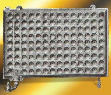
Figure 1
What is a Btu? It is an expression of energy. A man named Thomas Tredgold from England wrote a heating book back in the early 1800s called Warming and Ventilating of Buildings. In this book, he used the term “British Thermal Unit.” Tredgold took a POUND of water and heated it from 62°F to 63°F. He decided that one British Thermal Unit (Btu) was the amount of energy (heat) required to raise one POUND of water one degree Fahrenheit.
So this expression that we say and use dozens of times a day in the heating business was made up by some guy 200 years ago! We almost think of Btus as the Holy Grail of heating and in reality, it is just an expression of energy made up by a heating engineer who was trying to quantify what happens when one pound of water is heated up one degree Fahrenheit. That is why, when I was explaining to the contractor how to establish the load, we had to convert the gallons of water in the Jacuzzi to pounds of water in order to calculate the required Btu load.
If we were going to provide a circulator to pump boiler water through one side of the plate and frame heat exchanger to heat the Jacuzzi, we would have to calculate the necessary flow rate. To establish the proper flow, which is expressed as GPM (gallons per minute), we would start with the load. GPM = Btu/h / 500 x delta T; Btu/h is the load; 500 is the weight of a gallon of water (8.33) multiplied by sixty minutes in an hour (to convert Btus per hour into gallons per minute) and the delta T is the design temperature drop that the system water will experience as it delivers the design load (which is usually selected at 20°F).
So when establishing flow rate, it is necessary to convert gallons to pounds and introduce a time factor (60 minutes equals one hour). If we were to use the above Jacuzzi example to calculate the required GPM, it would look like this: 149,940 Btu/h divided by 10,000 = 14.9 GPM. (10,000 is 500 multiplied by the design temperature drop of 20°F).
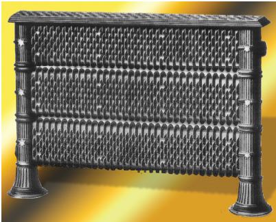
Figure 2