Parts 1 & 2, from the Jul/Aug and Sep/Oct 2021 Indoor Comfort can be found here.
Part 3, from the Nov/Dec 2021 Indoor Comfort can be found here.
Part 4, from the Jan/Feb 2022 Indoor Comfort can be found here.
Part 5, from the Mar/Apr 2022 Indoor Comfort can be found here.
Part 6, from the May/Jun 2022 Indoor Comfort can be found here.
Part 7, from the Jul/Aug 2022 Indoor Comfort can be found here.
Part 8, from the Sep/Oct 2022 Indoor Comfort can be found here.
Part 9, from the Nov/Dec 2022 Indoor Comfort can be found here.
Part 10, from the Jan/Feb 2023 Indoor Comfort can be found here.
Part 11, from the Mar/Apr 2023 Indoor Comfort can be found here.
As we look at modern systems and what specific problems they present, it’s important to understand the basic fundamentals associated with these systems.
Most of our modern heating equipment in some way or another involves electronics; along with the use of electronics is the use of flame rectification as a safety and flame-proving system. It doesn’t matter if it is a forced warm air furnace or a forced hot water boiler; the same basic system is used to perform safe ignition, and then consistent operation, throughout the entire call for heat.
There are, however, different ways it is applied, from intermittent pilot application to direct spark ignition and including hot surface ignition. Each system has its own distinct advantages and problems. Next in this series of resolving burner issues related to these systems, we offer corrections and diagnostics to help solve those problems.
We will start with the basics and go into operation, typical problems, diagnosis, troubleshooting procedures and a final solution to your particular problem. It can be easy to jump to conclusions and change parts until you hopefully solve the problem. That is, however, time-consuming and costly.
I invite you to visit our Facebook page, Timmie’s Tips On Gas, I look forward to seeing you there.
We are presently doing a series on Honeywell Smart Valve. Picking up where we left off in the last column, we will continue to cover Smart Valve Generation III, walking you through step-by-step troubleshooting with these controls. This article will need to be in perhaps two or three parts in order to illustrate the characteristics of this two-stage system and make them understood.
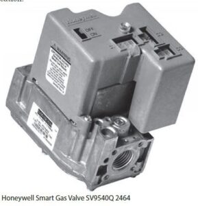
SV9540Q/ST9162 SmartValve Two Stage Heating
The system featured is the SmartValve™ using the SV9540Q two stage gas valve, used on Comfortmaker® furnace models NTVM/VNK. This series furnace is from International Comfort Products Corp. of Lewisburg, TN, and is now perhaps an older system but is still applicable for your education on these systems.
This instruction is not designed to be an installation or service manual for this furnace; rather, the purpose is to show the operation of a two-stage system. The troubleshooting of this system is also included and the features of this furnace will be presented to help provide an understanding of the two-stage system.
Unlike single-stage furnaces that deliver heat unevenly, this variable speed, two-stage gas furnace provides consistent heat and overall comfort. The difference is that the two-stage system produces heat for normal temperatures most of the time, automatically ramping up to higher heat production as needed. Unlike the single-stage, which heats fast and shuts down fast because it’s set for the coldest extremes, this system keeps the home warm without those annoying hot and cold spots.
The furnace is remarkably quiet, thanks to its variable speed circulation blower. It runs quietly in the slower speed, and gently—quietly—increases to the higher speed, as more heat is needed. You can even run the variable speed blower continuously at the lower speed to improve air quality around the clock. Pre-wiring also allows for addition of electronic air filters and humidification.
This 90+ system takes fuel efficiency to its highest level. The variable speed blower also adds an efficiency boost, cutting electrical costs up to 75% compared to standard blowers. This ECM DC voltage motor operates at 500 watts, at ½ speed 90 watts (economy).
Furnace Basics
The thermostat calls for heat and the gas valve is energized by the control system. The burners ignite and the induced draft fan draws the flame into and through the sealed primary heat exchanger. Then, the hot flue gases are pulled from the primary heat exchanger into the secondary heat exchanger, increasing efficiency. The variable speed blower moves another stream of air over the outside of both heat exchangers and brings the warm air into the home. The combustion products are safely vented outside.
This furnace features:
• Two-stage redundant gas valve
• Two-speed induced combustion fan
• Variable speed circulation blower motor
The Honeywell SV9541Q is a two-stage valve, which combines gas flow control and electronic intermittent pilot sequencing functions into a single unit. The Q3450 or 03480 Pilot hardware supplies the low voltage igniter, flame sensor and pilot burner. These ignition system controls provide all gas ignition safety functions by controlling gas flow, ignition source, and a 120 VAC or 240 VAC combustion air blower. The controls also monitor the appliance airflow proving switch and limit string to assure proper appliance operation, and provide pre-purge, post-purge and timed trial for pilot ignition with 100% shutoff and continuous retry. A diagnostic LED indicates system status.
Sequence of Operation
This system is unique as a two-stage system in that it starts on high fire and then, if there is no actual high fire call, it will go to low fire. This allows the development of some Delta “T” to develop in the plenum and duct system (as this is a condensing furnace, it also allows some development of flue gas vaporization). Figure 1 illustrates the sequence as outlined step-by-step below with a bar graph.
(A more specific application to the ComfortMaker Furnace will be illustrated in the next issue).
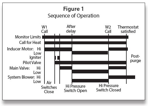
The sequence of operation is as follows:
• Thermostat call—W1
• Combustion air blower—high speed
• Air proving switches
• Pilot flame lit and proved
• Main burner—high fire
• After delay—low speed combustion blower and low fire
• Fan timer
• Circulating fan—low speed
• Thermostat call—W1/W2
• Combustion air blower—high speed
• Air proving switches
• Main burner—high fire
• Circulating fan—high speed
Controls & Accessories
Thermostat
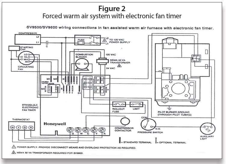
The two-stage furnace control will operate with a two stage-heating thermostat and will provide two-stage heating operation. For two-stage thermostat installations, the R, W1 and W2 wires from the thermostat connect to the R, W1 and W2 connections on the furnace control as shown in Figure 2. During operation, the furnace will shift from low fire to high fire as requested by the thermostat. The thermostat heat anticipators should be adjusted to a .10 setting.
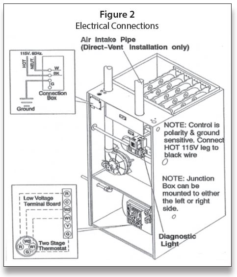
Line voltage connection is also shown in Figure 2; it is important to follow correct polarity, as electronic controls may not function correctly with reverse polarity.
Low voltage connections to furnace must be made on terminal board to fan control.
Optional Equipment
All wiring from furnace to optional equipment must conform to local codes or, in the absence of local codes, the applicable national codes. Install wiring in accordance with manufacturer’s instructions.
Humidifier/Electronic Air Cleaner
The furnace is wired for 120 VAC humidifier and/or electronic air cleaner connection.
The fan control is wired for 24 VAC normally open (N/O) dehumidistat connection. Connect dehumidistat to the Y terminal and the ¼” male quick connect Y2 terminal on the fan control (scan the QR code at left to see the complete Furnace Wiring Diagram). A 20% reduction of cooling airflow will occur when the Y2 dehumidistat terminal is energized during a call for cooling from the thermostat.
Fan Control
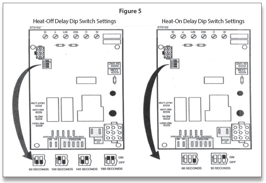
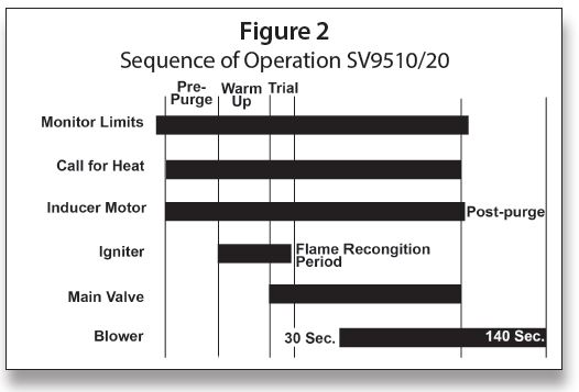
The fan control is preset at the factory with an adjustable blower On delay of 30 seconds in the heating mode. The blower Off timing is preset at 140 seconds. If desired, the fan On delay and Off delay can be reset (See Figure 3 and Figure 4 for location of dip switches) to obtain the longest delay times while still maintaining comfort levels (scan QR code at left for Furnace Wiring Diagram).
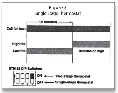
NOTE: To achieve maximum efficiency, it is recommended that the fan control be set to turn on at 30 seconds after the burners light.
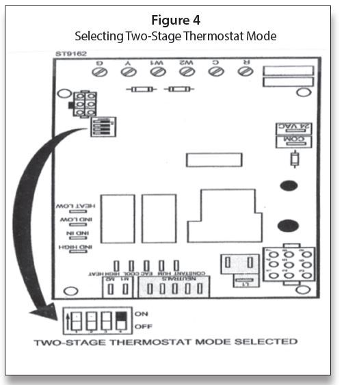
The ST9162 can be used as a two-stage or single-stage. When the choice is made, the dip switches on the EFT must be set as shown in Figure 3.
The dip switch settings for Heat-On and Heat-Off delay are shown in Figure 5.
In the next issue, we will pick up with SmartValve Two Stage with Comfortmaker Sequence of Operation. ICM
Parts 1 & 2, from the Jul/Aug and Sep/Oct 2021 Indoor Comfort can be found here.
Part 3, from the Nov/Dec 2021 Indoor Comfort can be found here.
Part 4, from the Jan/Feb 2022 Indoor Comfort can be found here.
Part 5, from the Mar/Apr 2022 Indoor Comfort can be found here.
Part 6, from the May/Jun 2022 Indoor Comfort can be found here.
Part 7, from the Jul/Aug 2022 Indoor Comfort can be found here.
Part 8, from the Sep/Oct 2022 Indoor Comfort can be found here.
Part 9, from the Nov/Dec 2022 Indoor Comfort can be found here.
Part 10, from the Jan/Feb 2023 Indoor Comfort can be found here.
As we look at modern systems and what specific problems they present, it’s important to understand the basic fundamentals associated with these systems.
Most of our modern heating equipment in some way or another involves electronics; along with the use of electronics is the use of flame rectification as a safety and flame-proving system. It doesn’t matter if it is a forced warm air furnace or a forced hot water boiler; the same basic system is used to perform safe ignition, and then consistent operation, throughout the entire call for heat.
There are, however, different ways it is applied, from intermittent pilot application to direct spark ignition and including hot surface ignition. Each system has its own distinct advantages and problems. Next in this series of resolving burner issues related to these systems, we will give you corrections and diagnostics to help solve those problems.
We will start with the basics and go into operation, typical problems, diagnosis, troubleshooting procedures and a final solution to your particular problem. It can be easy to jump to conclusions and change parts until you hopefully solve the problem with these systems. That is, however, time-consuming and costly.
I invite you to visit our new Facebook page, Timmie’s Tips On Gas. I look forward to seeing you there.
We are presently doing a series on Honeywell Smart Valve. Picking up where we left off in the last column, we will continue to cover Smart Valve Generation III, walking you through step-by-step troubleshooting with these controls.
Application
The SV9440, SV9540, and SV9640 SmartValve™
System Controls combine gas flow control and electronic intermittent pilot sequencing functions into a single unit. The Q3450 or Q3480 Pilot hardware supplies the low-voltage igniter, flame sensor and pilot burner much the same as Generation I and II. These ignition system controls provide all gas ignition safety functions by controlling gas flow, ignition source and 120 VAC or 240 VAC combustion air blowers. The controls also monitor the appliance airflow proving switch and limit string to assure proper appliance operation and provide pre-purge, post-purge and timed trial for pilot ignition with 100% shutoff and continuous retry. A diagnostic LED indicates system status.
These controls communicate directly with an electronic fan timer (ST9160 Electronic Fan Timer for single stage applications; ST9162 Electronic Fan Timer for two-stage applications) in typical forced warm air furnace applications. They also interface with the 208907 Terminal Board, providing compatibility with power-stealing thermostats or they directly interface with the appropriate power supplies and a system thermostat for additional appliance applications. When controlled directly by a thermostat, these controls do not provide a post-purge function because power to the control is removed when the thermostat call for heat ends.
The SV9440, SV9540 and SV9640 Systems are suitable for a wide range of fan-assisted combustion gas-fired appliances including furnaces, rooftop furnaces, boilers, unit heaters, infrared heaters, water heaters and commercial cooking appliances. The appliance manufacturer determines the specific application of the SmartValve System.
SmartValve System controls are available in a range of valve capacities. Scan this QR code to see:
Table 1: Valve capacity
Table 2: Gas capacity conversion factors
Table 3: Model number suffix designations (the suffix letter indicates temperature range and regulator type)
This is very similar in operation to Generation I and II using a pilot system. It has the 90-second trial for ignition with the five-minute shutdown before retry. Pre-purge time is 15 seconds; post-purge is 30 seconds (not available when SmartValve System Control is connected directly to the thermostat). Flame failure response time is 1.6 seconds at 2 μA.
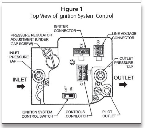
Figure 1 illustrates a top view of the valves; the only difference with this valve is that the igniter output C2 is 24 VAC. There is also 24 VAC interrupter fed to the C1-8 pin that was not used on the SV9510/9520 series SmartValves.
Wiring Diagrams
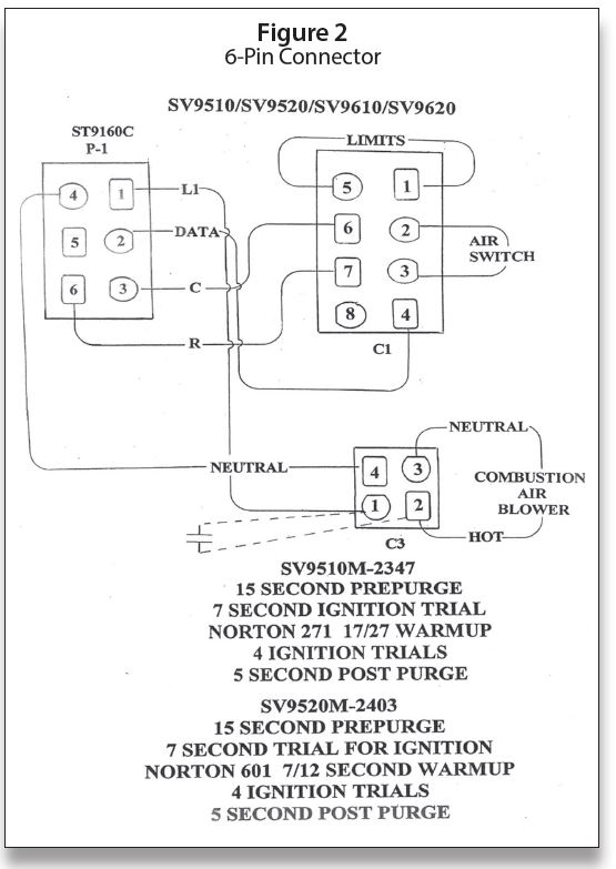
As we look at Figure 2 with a forced warm air furnace, the wiring is very similar to wiring on the SV9510/9520 series SmartValve. The exceptions are the 24 VAC C2 igniter hook-up on the SmartValve and the use of C1-8 to P1-5 for 24 VAC interrupted 24 volts. The sequence of operation is the same as using the S9160 Electronic Fan Timer as shown in Figure 2.
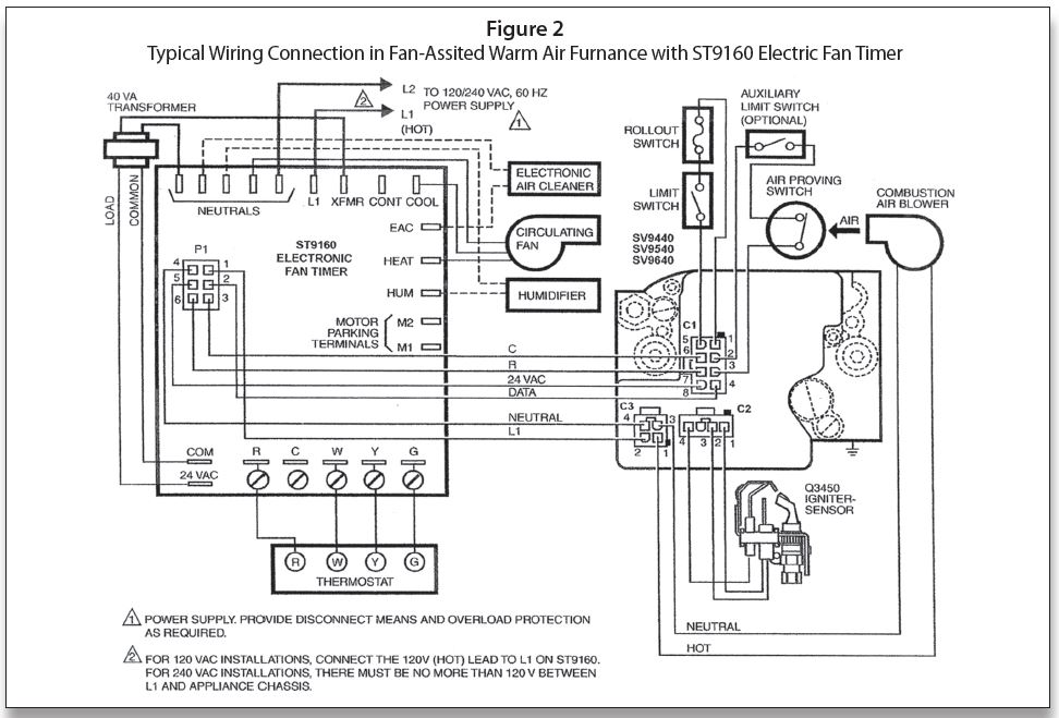
Figure 3 shows SmartValve 9440/9540/9640 used with Honeywell R8285D Boiler Control Center. Once again, this is very similar in operation to the SV9510/9520 Series of SmartValve. The difference is 24 VAC being fed direct from the “R” terminal on the R8285D to C1-8 on the SmartValve. The R/DATA connection is the interrupted 24 volts as the 120 VAC is fed from the junction box direct to C3-2/C3-4. The rest of the sequence is similar to Figure 3.
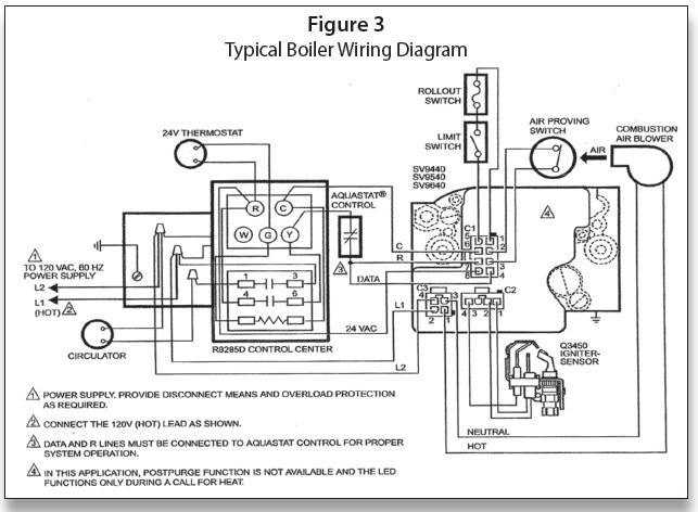
Figure 4 shows a direct connection from the thermostat to SmartValve. This wiring setup could be used with a steam system by wiring the LWCO and Pressuretrol in place of the limit switch. The 120 VAC is fed direct to C3-2/C3-4 from the junction box. The 24 VAC is fed direct from the transformer to C1-8. The R/DATA/W is the interrupted circuit.
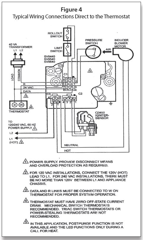
Figure 5 shows the SV9440/9540/9640 with the 208907 terminal board that allows compatibility with power stealing thermostats.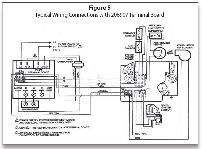
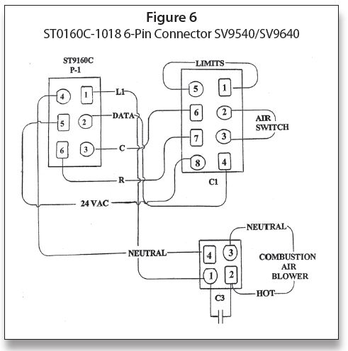
Figure 6 shows the various pin locations and the shape of the pins on both the EFT and the SmartValve.
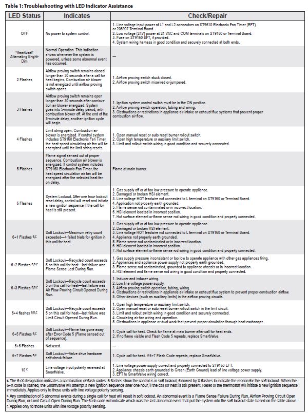
Scan this QR code to see Figure 7, which is the sequence of operation for the ST9160 EFT or 208907 terminal boards. These boards are used with the SV9541 and SV9641 SmartValve™. When troubleshooting, make note of the igniter turning off after 30 seconds into the 90-second trail for ignition, and remaining off for approximately 25 seconds. It then should come back on for the final 30 seconds of the 90-second trail. The pilot valve is energized during the entire trail for ignition. If the system fails to light after the 90-second trial for ignition, it will go into a five-minute delay and then retry for another 90-second trial. This process will continue until the system finally lights and the main burner is on.

Scan this QR code to read more about troubleshooting with LED indicator assistance for ignition controls using ST9160 fan timer or 208907 terminal board. ICM
Parts 1 & 2, from the Jul/Aug and Sep/Oct 2021 Indoor Comfort can be found here.
Part 3, from the Nov/Dec 2021 Indoor Comfort can be found here.
Part 4, from the Jan/Feb 2022 Indoor Comfort can be found here.
Part 5, from the Mar/Apr 2022 Indoor Comfort can be found here.
Part 6, from the May/Jun 2022 Indoor Comfort can be found here.
Part 7, from the Jul/Aug 2022 Indoor Comfort can be found here.
Part 8, from the Sep/Oct 2022 Indoor Comfort can be found here.
Part 9, from the Nov/Dec 2022 Indoor Comfort can be found here.
As we look into some more modern systems and what specific problems they present, it is important to understand the basic fundamentals associated with these systems. Most of our modern heating equipment in some way or another involves electronics and the use of flame rectification as a safety and flame-proving system.
It doesn’t matter if it is a forced warm air furnace or a forced hot water boiler—the same basic system is used to perform safe ignition followed by consistent operation throughout the entire call for heat.
There are, however, different ways the system is applied from intermittent pilot application to direct spark ignition and including hot surface ignition (HSI). Each has its own distinct advantages and problems. We’ll now attempt to resolve those burner problems related to these systems, as well as offer corrections and diagnostics.
We will start with the basics and then continue to operation, typical problems, diagnosis, troubleshooting procedures and a final solution to a particular problem. It’s easy to jump to conclusions with these systems and just change parts to hopefully solve a problem. That is, however, time-consuming and costly.
I invite you to visit our new Facebook page Timmie’s Tips on Gas. I look forward to seeing you there.
We are presently doing a series on Honeywell SmartValve; in this article we will cover SmartValve Third Generation and walk you through the step-by-step process of operation with these controls.
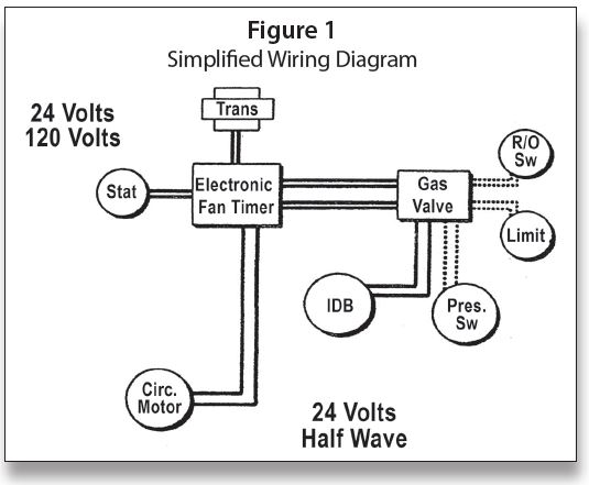
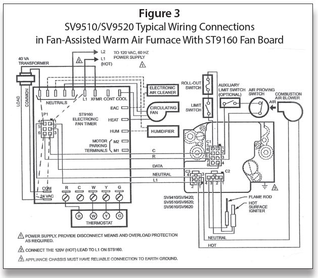
Something new has been added to be able to distinguish between controls and their functions. They are using different voltages and rectifications to carry DATA signals. This helps to define the difference electronically between limits and other controls in the system. This is illustrated in Figure 1: Simplified Wiring Diagram.
This is nothing to get concerned about, as a switch is either “open” or “closed” and the voltage readings are always this—across an open switch you will read “voltage” and across a closed switch you will read “zero.” To troubleshoot, as always, you can jump out switches.
Here are a few new things to keep in mind while troubleshooting:
• Air proving switch and limit string use 24 volt half wave rectified current
• Volt meter checks will give different readings
Figures 2 and 3 are from the November/December column. They are necessary in order to trace through the diagram.
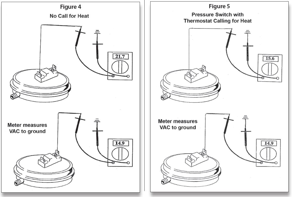
With no call for heat in Figure 4, the voltages shown were recorded. To be able to see the effect of operation on the pressure switch as to voltage readings, I simulated blocked pressure switch tubing in Figure 5; all that changed was the readings—in both cases it was an open pressure switch.
Be careful to wait for the prepurge and igniter warm up time when diagnosing problems. Depending on those times, it can be up to a minute before you will have burner ignition. These systems also have a very short trial for ignition. Be aware of the sequence of operation and watch for any deviations from the normal operation.
For a trouble diagnosis, refer to the specific LED code as outlined in Table 1: Troubleshooting with LED Indicator Assistance. Newer versions have the expanded 6 code diagnostics with the 10 flash indicating reverse polarity.
In addition to the codes and other diagnostics available, checks can be done with a multimeter. Using the diagram in Figure 3, the following checks should be made for Direct Spark Ignition (DSI) igniter troubleshooting:
• Wait for pre-purge and igniter warm-up
• Short trial for ignition
• Watch for any deviation from sequence of operation
Here are more in-depth directions for troubleshooting:
1. L1 to Neutral should have 120 VAC; L1 to ground should read 120 VAC; if not then polarity may be reversed.
2. XFMR (transformer) to Neutral should have 120 VAC.
3. COM – 24 VAC should have 24 volts AC.
4. With a call for heat from the thermostat or by jumping “R” to “W,” you should have 120 VAC at C3-1/C3-2 and the Combustion Air Blower should be running.
5. Accounting for the time for prepurge, you should have 120 VAC at C2-1/C2-3 and the igniter should be glowing and the Air Proving Switch should be closed.
6. Accounting for igniter warm-up time, there should be 24VAC at C1-7/C1-6 and the Smart Valve should be energized. If not, check the limit switch, roll out switch or air proving switch string for an open switch.
7. When the burner is up and running, you should have a DATA signal coming out of C1-4 and going into P1-2 on the EFT. After the fan delay time is satisfied, the Circulating Fan should be on—if not, check for 120 VAC from the HEAT terminal on the EFT; it should be set to Neutral. If you have power to the fan and it is not running, replace the fan.
Also keep in mind:
• Use troubleshooting table in spec sheet and LED
• Using both should lead you to the trouble
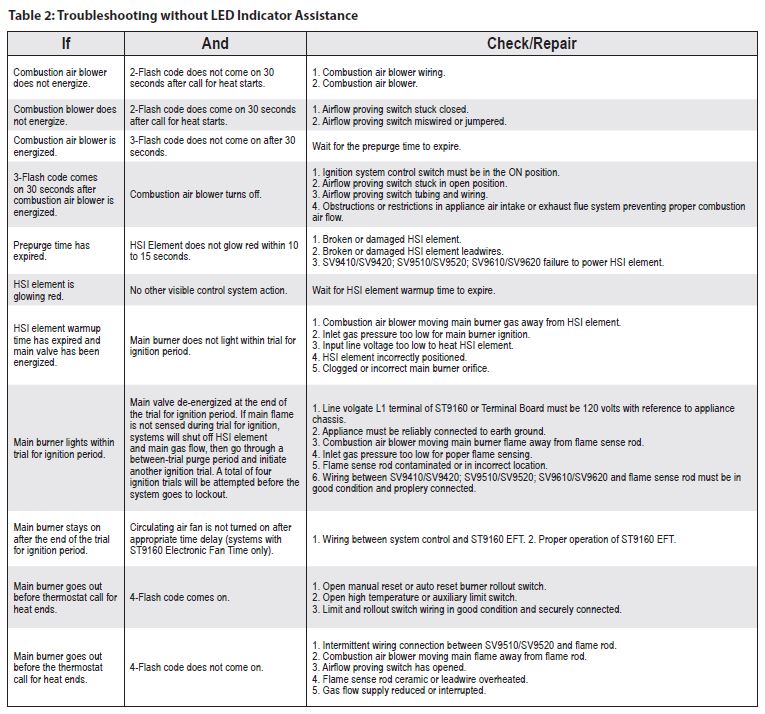
These LED codes are for the older version Smart-Valve, the newer ones have the extended code as shown in Table 1. There is also a procedure for troubleshooting without the codes just in case they are not working or the power was shut off before the technician arrived to fix the problem. It is illustrated in Table 2. ICM
Part 9, from the Nov/Dec 2022 Indoor Comfort
Parts 1 & 2, from the Jul/Aug and Sep/Oct 2021 Indoor Comfort can be found here.
Part 3, from the Nov/Dec 2021 Indoor Comfort can be found here.
Part 4, from the Jan/Feb 2022 Indoor Comfort can be found here.
Part 5, from the Mar/Apr 2022 Indoor Comfort can be found here.
Part 6, from the May/Jun 2022 Indoor Comfort can be found here.
Part 7, from the Jul/Aug 2022 Indoor Comfort can be found here.
Part 8, from the Sep/Oct 2022 Indoor Comfort can be found here.
As we look into some more modern systems and what specific problems they present, it is important to understand the basic fundamentals associated with these systems. Most of our modern heating equipment in some way or another involves electronics and the use of flame rectification as a safety and flame-proving system.
It doesn’t matter if it is a forced warm air furnace or a forced hot water boiler—the same basic system is used to perform safe ignition followed by consistent operation throughout the entire call for heat.
There are, however, different ways the system is applied from intermittent pilot application to direct spark ignition and including hot surface ignition (HSI). Each has its own distinct advantages and problems. We’ll now attempt to resolve those burner problems related to these systems, as well as offer corrections and diagnostics.
We will start with the basics and then continue to operation, typical problems, diagnosis, troubleshooting procedures and a final solution to a particular problem. It’s easy to jump to conclusions with these systems and just change parts to hopefully solve a problem. That is, however, time-consuming and costly.
I invite you to visit our new Facebook page. I look forward to seeing you there.
We are presently doing a series on Honeywell SmartValve; in this article, we will cover SmartValve Third Generation and walk you through the step-by-step process of operation with these controls.
SV9510/SV9520 Sequence of Operation
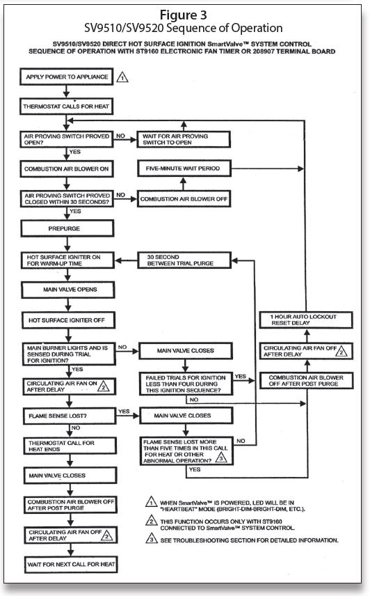
Figure 1 is the sequence of operation for SV9510 and SV9520 SmartValve. The various diagrams featured in this article will show you the circuits involved.
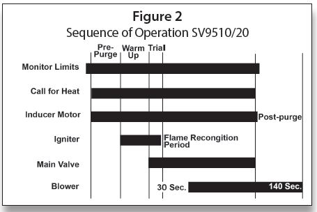
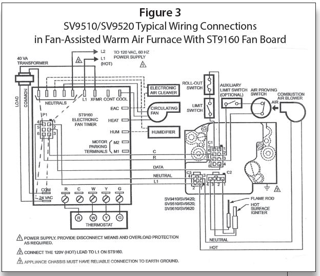
Referring to Figure 1 and Figure 2 for the Sequence of Operation and to Figure 3 for a diagram, let’s go through the Sequence of Operation.
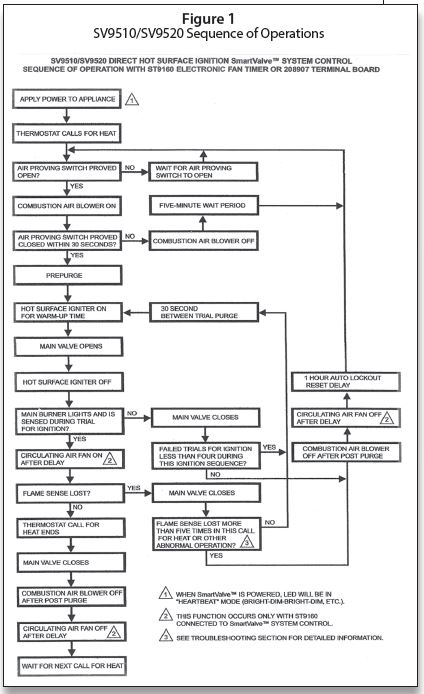
When power to both 120 VAC and 24 VAC is applied to the system, the LED on the SmartValve will be pulsing “in the Heartbeat mode”—bright-dim-bright-dim, etc. L1 (Hot) is fed to L1 on the EFT. Then 120 VAC is fed from XFMR (transformer) to an external 40 VA or 50 VA transformers, depending on which valve. From the transformer, 24 VAC is fed to the 24VAC/Com terminals on the EFT.
The dotted lines in Figure 3 are my additions to illustrate the printed circuit board feed from L1 to P1-1 120 VAC, and from neutral to P1-4, as well as the 24 VAC (Hot) from terminal 24VAC to P1-6 and the common (COM) to P1-3. The ST9160 Electronic Fan Timer will be covered in a later section.
The setup for this wiring shown in Figure 3 has the 120 VAC to the SmartValve interrupted and 24 VAC is fed direct on the “R” wire to C1-7 and the “C” to C1-6 on the SmartValve. On a call for heat, a circuit is completed through R and W on the ST9160 the air-proving switch, which must then prove open in 30 seconds. If it does, then 120 VAC is fed from P1-1 to C3-2 and back on neutral from C3-4 to P1-4. Then 120 VAC is fed from C3-1 to the Combustion Air Blower and back to neutral on C3-3. Then the prepurge begins.
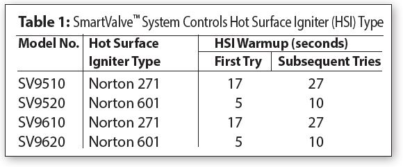
At the end of the prepurge, the HSI warm-up starts. The igniter warm-up time for the Norton 271 (used with SV9510) is 17 seconds on the first try and 27 seconds on subsequent tries. The Norton 601 (used with SV9520) warm-up is five seconds on the first try and then 10 seconds on subsequent tries.
The main valve opens and ignition takes place. The flame rod proves the burner flame and the DATA signal is fed from C1-4 to P1-2 to start the fan-on time sequence. The fan will usually come on in 30 to 60 seconds.
When the call for heat ends, and R and W breaks, power to the Combustion Air Blower ceases after post-purge. The air proving switch opens and the DATA signal ceases; the Electronic Fan Timer goes to the dip switch set fan-off run time. At the end of that time, everything is ready for the next call for heat.
Figure 4 shows how the 208907 terminal board allows compatibility with power-stealing thermostats. Many of the control boards cannot be used with power-stealing thermostats unless there is an isolating relay used or a 100 ohm 10 watt resistor placed across W and C.
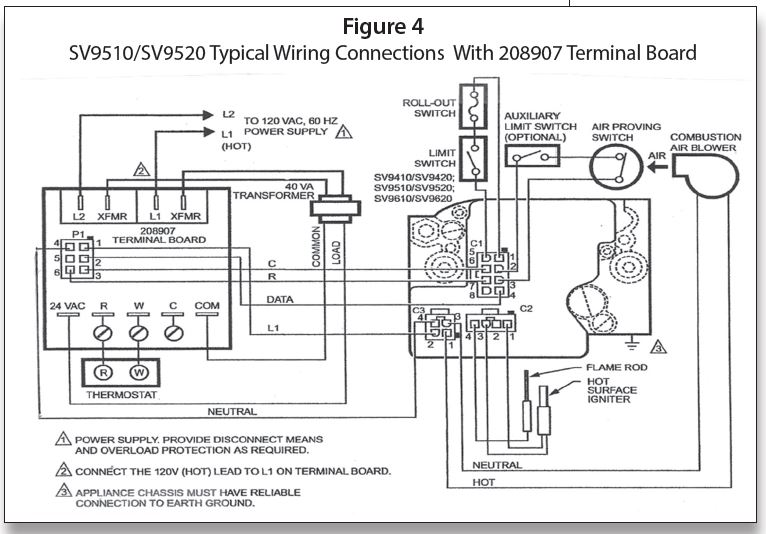
Figure 5 shows a typical wiring diagram with a Forced Hot Water System using a R8285D Honeywell Control Center. With this setup, the 120 VAC is fed direct from the junction box to C3-2 (Hot)/C3-4 (Neutral); in this case, the 24 VAC is interrupted.
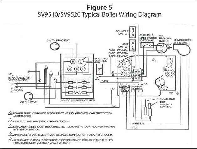
L1 Hot is also fed to Pin 3 on the R8285; also, 24 VAC is fed to Pin 4. On a call for heat from the thermostat, 24 VAC is fed from “R” through the thermostat to “G,” then to the relay coil and back to “C.” This brings in the two sets of relay contacts—1–3 sends 120 VAC to the circulator; 4–6 takes 24 VAC from “R” to “Y” through the aquastat control (high limit) to the R and DATA wire C1-7 and C1-4 (DATA). The sequence after that is the same as the sequence for Figure 3.
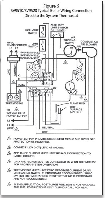
Figure 6 is an example of wiring direct to the thermostat. This setup could also be used for a steam system by adding a Low Water Cut-Off and Pressuretrol in place of the limit switch.
The 24 VAC is again interrupted and the 120 VAC is fed direct to C3-2 and C3-4. In many instances, a jumper from C1-4 to C1-7 may accomplish the wiring from the DATA to “R” wire. Pay particular attention to the triangle notes 1–6 in Figure 6.
In the next article we will discuss troubleshooting the SmartValve Third Generation. ICM
Part 8, from the Sep/Oct 2022 Indoor Comfort
Parts 1 & 2, from the Jul/Aug and Sep/Oct 2021 Indoor Comfort can be found here.
Part 3, from the Nov/Dec 2021 Indoor Comfort can be found here.
Part 4, from the Jan/Feb 2022 Indoor Comfort can be found here.
Part 5, from the Mar/Apr 2022 Indoor Comfort can be found here.
Part 6, from the May/Jun 2022 Indoor Comfort can be found here.
Part 7, from the Jul/Aug 2022 Indoor Comfort can be found here.
As we look into some more modern systems and what specific problems they present, it is important to understand the basic fundamentals associated with these systems. Most of our modern heating equipment in some way or another involves electronics and the use of flame rectification as a safety and flame-proving system.
It doesn’t matter if it is a forced warm air furnace or a forced hot water boiler—the same basic system is used to perform safe ignition followed by consistent operation throughout the entire call for heat.
There are, however, different ways the system is applied from intermittent pilot application to direct spark ignition and including hot surface ignition (HSI). Each has its own distinct advantages and problems. We’ll now attempt to resolve those burner problems related to these systems, as well as offer corrections and diagnostics.
We will start with the basics and then continue to operation, typical problems, diagnosis, troubleshooting procedures and a final solution to a particular problem. It’s easy to jump to conclusions with these systems and just change parts to hopefully solve a problem. That is, however, time-consuming and costly.
I invite you to visit our new Facebook page Timmie’s Tips on Gas. I look forward to seeing you there.
We are presently doing a series on Honeywell Smart Valve™. We will pick up where we left off in the last article and cover Smart Valve™ The Third Generation. We will walk you through the step-by-step process of operation with these controls.
SmartValve™ Third Generation
The third generation of SmartValve™ became available to the original equipment manufacturers (OEMs) in late 1998/early 1999. It includes the SV9510/SV9520 and SV9610/SV9620.
The SmartValve™ works in conjunction with the Honeywell Electronic Fan Timer ST9160. It uses direct burner ignition line voltage igniters, such as the Norton 271, which has been used on HSI for many years. The new igniter used is the Norton 601.
The SV9540/SV9640 is also used with the EFT ST9160 control. It uses the same 24-volt igniter system used on SmartValve™ Generation I and II.
There is also a SmartValve™ SV9540Q used with Electronic Fan Time ST9162. This is a two-stage system that will be covered in a later discussion.
SV9510/SV9520; SV9610/SV9620 SmartValve™ System Controls
Application
The SV9510/SV9520 and SV9610/SV9620 SmartValve™ System Controls combine gas flow control and electronic direct main burner ignition sequencing functions into a single unit. The ignition source is a 120V HSI lighting the main burner flame. Two types of 120V igniters may be used, as seen in Table 1.
The control provides all gas ignition safety functions by controlling gas flow, ignition source and a 120 VAC combustion air blower. The control also monitors the appliance airflow-proving switch and limit string to assure proper appliance operation.
The SmartValve™ System Controls provide pre-purge, post-purge and timed trial for ignition with multiple ignition trials and auto reset from lockout. Diagnostic LED indicates system status.
The control communicates directly with the ST9160 Electronic Fan Timer (EFT) in typical forced warm air furnace applications. It will also interface with the 208907 Terminal Board, providing compatibility with power-stealing thermostats. Alternately, it directly interfaces with the appropriate power supplies and a system thermostat for additional appliance applications. When controlled directly by a thermostat, the control does not provide a post-purge function, as power to the control is removed when the thermostat’s call for heat ends.
This system is suitable for a wide range of fan-assisted, combustion, gas-fired appliances including furnaces, rooftop furnaces, boilers, unit heaters, infrared heaters, water heaters and commercial cooking appliances.
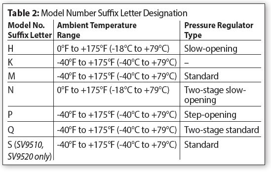
The specific application of the SmartValve™ System is the responsibility of the appliance manufacturer. See Table 2 for temperature ranges and regulator types.
Line voltage polarity sensing models monitor the line voltage input connection to assure line voltage polarity is correct. If line voltage polarity is incorrect, the LED diagnosis code will flash and the control will not respond to the call for heat. These models also provide added LED diagnostic codes (“6+”) to indicate the reason the control has moved to the lockout state.
Depending on models, various timings are available, such as 15 or 30 seconds pre-purge; post-purge five seconds (typical depending on model; this is not available when the SmartValve™ is connected directly to the thermostat); five, seven or nine seconds trial for ignition; 60-minute soft lockout; three retries; four trials before lockout. The other unusual feature is that the draft inducer is now controlled from the SmartValve™; depending on the version, this is accomplished by either interrupting the 120 volts or 24-volt signal. This will be defined as each diagram is discussed.
The capacities on SV9510, 20 and 40½” x ½” 200,000 BTUs maximum and on the SV9610, 20, 40¾” x ¾” is 415,000 BTUs.
Figure 1 is an illustration of the top view of the valves. The C3 connector is for 120-volt power, and this is also the feed for the draft inducer. The C2 connector is for the 120-volt HSI, either the Norton 271 Silicon Carbide in the case of the SV9510, or the Norton 601 120 volt Silicon Nitride Igniter used only with the SV9520 model. The C1 connector is the low voltage 24-volt AC hookup.
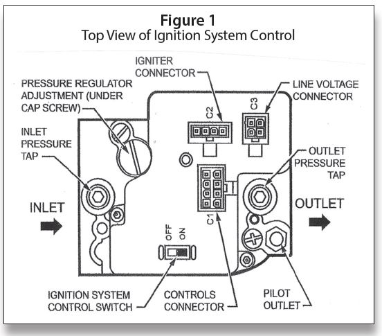
The designation of pin numbers for the C1 and C3 connectors on the SmartValve™ and the 6-pin connector on the ST9160 Electronic Fan Timer are illustrated in Figure 2.
Converting Ignition System Control
From Natural Gas to LP Gas Application (or LP Gas to Natural Gas Application)
Always change the main burner orifices as provided by the manufacturer of the equipment being converted. Ignition system controls are factory-set for natural (and manufactured) or LP gas. Do not attempt to use an ignition system control set for natural (manufactured) gas on LP gas, or an ignition system control set for LP gas on natural (manufactured) gas.
Ignition system controls with standard or slow opening regulators (SV9510M, H/ SV9520M, H, K) can be converted from one gas to the other with a conversion kit (ordered separately). Order part No. 393691 to convert from natural (manufactured) to LP gas; order part No. 394588 to convert from LP to natural (manufactured) gas.
Two-stage ignition system controls (those with N and Q suffix letters) can be converted using a conversion kit (ordered separately). Order part No. 396021 to convert from natural (manufactured) to LP gas; order part No. 396025 to convert from LP to natural (manufactured) gas.
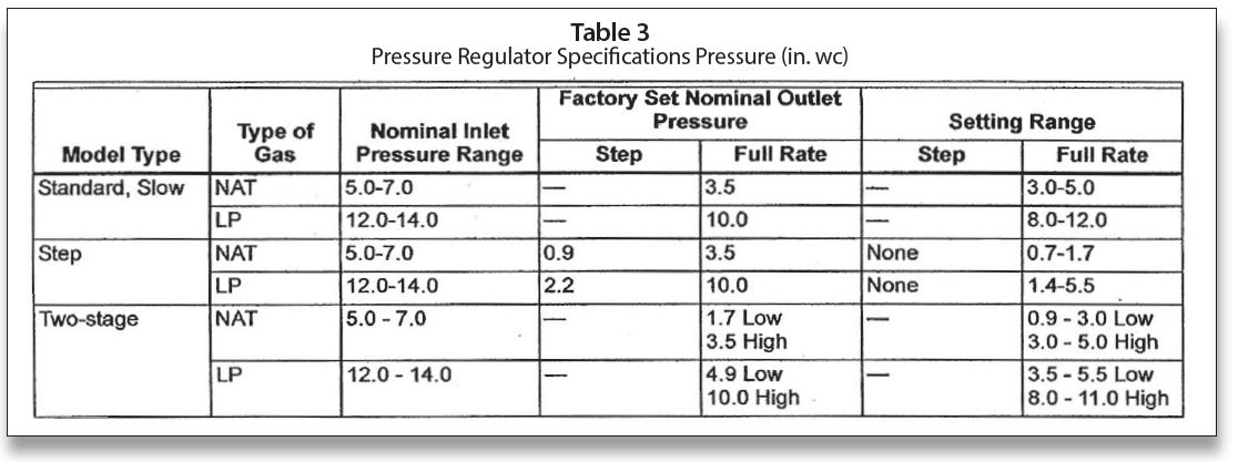
IMPORTANT: Ignition system controls with step-opening regulators (SV9510P/ SV9520P) cannot be field-converted to LP or natural gas. See Table 3 for pressure settings for valves.
SV9510/SV9520 Sequence of Operation
Figure 3 is the sequence of operation for the SV9510 and SV9520 SmartValve™.
Training
Finally, I love to teach and would love to have you come and join us for some training. We also conduct seminars on the following topics and many others:
Five-Day Course
• Fundamentals of Gas
• Circuitry & Troubleshooting
• Hydronic Controls
• Electric Ignition Systems
• Advanced Electric Ignition Systems
One-Day Course
• Powerpile Systems
Three-Day Course
• Combustion Testing Design Gas Equipment
• Conversion Burners
Four-Day Course Designed for Your Specific Need
• Modulating/Condensing Boilers
For more information, call 401-437-0557 or write to:
Gas Appliance Service Training & Consulting
42 Village Drive, Riverside, RI 02915.
E-mail: timmcelwain@gastcri.com. ICM
Part 7, from the Jul/Aug 2022 Indoor Comfort
Parts 1 & 2, from the Jul/Aug and Sep/Oct 2021 Indoor Comfort can be found here.
Part 3, from the Nov/Dec 2021 Indoor Comfort can be found here.
Part 4, from the Jan/Feb 2022 Indoor Comfort can be found here.
Part 5, from the Mar/Apr 2022 Indoor Comfort can be found here.
Part 6, from the May/Jun 2022 Indoor Comfort can be found here.
As we look into some more modern systems and what specific problems they present, it is important to understand the basic fundamentals associated with these systems. Most of our modern heating equipment in some way or another involves electronics and the use of flame rectification as a safety and flame-proving system.
It doesn’t matter if it is a forced warm air furnace or a forced hot water boiler—the same basic system is used to perform safe ignition followed by consistent operation throughout the entire call for heat.
There are, however, different ways the system is applied from intermittent pilot application to direct spark ignition and including hot surface ignition. Each has its own distinct advantages and problems. We’ll now attempt to resolve those burner problems related to these systems, as well as offer corrections and diagnostics.
We will start with the basics and then continue to operation, typical problems, diagnosis, troubleshooting procedures and a final solution to a particular problem. It’s easy to jump to conclusions with these systems and just change parts to hopefully solve a problem. That is, however, time-consuming and costly.
I invite you to visit our new Facebook page Timmie’s Tips on Gas. I look forward to seeing you there.
Forced hot water boiler wiring diagram
I want to emphasize once again how important knowing the sequence of operation of equipment is to proper diagnosis of problems. We are now going to go over sequence of operation on a forced hot water system. In the last article we covered forced warm air.
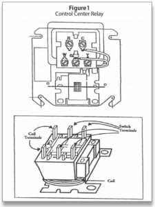
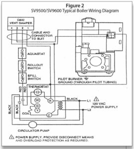
The system shown in Figure 2 is using a control center (transformer and relay) shown in Figure 1. The same control, when used on a forced warm air system, is called a “fan control center.” It is important to note that the wiring is different for a boiler versus a furnace. The use of a control center on a warm air furnace or boiler is a convenient place to connect wires and also makes for easier troubleshooting.
The transformer has the wiring connections attached. The “R” and “C” terminals are the only actual voltage connections. The other terminals are for wiring connections. The relay part of the control center is field replaceable. The best thing is to carry a SPDT relay, which can be used to replace another SPDT or SPST relay without any wiring changes in the junction box. Being able to stay out of the junction box is very important as the possibilities of connections coming loose are increased when you have to get into the “J” Box.
In addition to the “control center,” we have a Generation I SmartValve™ and a Honeywell D-892 vent damper. In Figure 2, the vent damper is shown with only the external wiring connections. It is sometimes difficult to imagine what is going on inside a control if the internal connections and components are not shown. I find that showing the internal operation of controls makes following the electrical path easier.
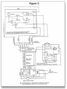
In Figure 3, we show the internal connections of the D892 vent damper. The sequence of operation we are going to follow is best understood using Figure 3. The purpose of the vent damper is to increase the efficiency of the equipment a little more by shutting down the standby loss from the boiler during the time when the thermostat is not calling. Anytime a vent damper is used, it must have an interlock circuit to ensure that the unit does not fire with the damper closed. This particular damper from Honeywell is powered closed and must have a continuous uninterrupted 24 volts at all times. When a call for heat takes place, the motor in the damper is de-energized and it will spring open. This, in turn, will activate the two N.O. sides of the switches (end switches).
In addition to power being required to the vent damper on a continuous basis, the SmartValve™ must also have an uninterrupted 24 volts at all times. When the SmartValve™ is used on a boiler application, the Electronic Fan Timer (EFT) output from the SmartValve™ is not used. The EFT output is only needed with a furnace.
Sequence of operation
The sequence of operation with this example is as follows:
1. Uninterrupted 24 VAC from R/C on Control Center is fed to SmartValve™.
2. 24 VAC to terminal 1 on the vent damper through the orange wire, through the right-hand side of relay Kl (closed) the NC set of S3 contacts to T2 through the motor to T1 and returning back to terminal 4 on the yellow wire. This powers the motor and damper is closed.
3. On a call for heat, the coil in the control center is powered and two sets of contacts close.
a. The left-hand set takes 120 VAC from L1 to Circulator Pump and back to L2.
b. The other set takes 24 VAC from R through spill switch, rollout switch and aquastat to terminal 2 on the vent damper.
4. The 24 VAC on 2 (black wire) goes to energize relay K1 in vent damper actuator and back to 4 on the yellow wire, the right-hand K1 switch is opened breaking power to the damper motor K1 switch now makes the left-hand side. The motor is now de-energized and the spring now opens the vent damper (mechanical action); the two normally open (N.O.) contacts close S1 and S2.
5. The relay stays powered through terminal 2 (black wire) during the entire call for heat unless one of the safeties opens.
6. The S1 and S2 (SPDT) set are in series and when the motor de-energizes and the spring opens the damper, they provide the path for 24 VAC through the left-hand side of K1 through S1 and S2 on the blue wire terminal to 3 on the damper powering the SmartValve™.
7. Now 24 VAC is fed out of terminal 3 on the vent damper to the interrupted leg of SmartValve™. The burner is now on.
8. When the call for heat ends, the control center relay coil is de-energized, as is also the K1 relay coil and the circulator shuts down. When K1 is de-energized, the K1 relay switches back to the right-hand side and the motor is powered closed. End switch contacts S1 and S2 are now tripped back to NC position.
9. Power is shut off to the interrupted leg of SmartValve™ and the burner shuts down.
It should be noted that switch S3 stays NC at all times unless the service switch is tripped; in that case it will de-energize the motor and the damper will now open manually.
The resistor R1 is to prevent power stealing programmable thermostats from energizing the damper when there is no call for heat. This is one of the phenomena of some power-stealing-type thermostats. ICM
Part VI, from the May/Jun 2022 Indoor Comfort
Parts I & II, from the Jul/Aug and Sep/Oct 2021 Indoor Comfort can be found here.
Part III, from the Nov/Dec 2021 Indoor Comfort can be found here.
Part IV, from the Jan/Feb 2022 Indoor Comfort can be found here.
Part V, from the Mar/Apr 2022 Indoor Comfort can be found here.
As we look into some more modern systems and what specific problems they present, it is important to understand the basic fundamentals associated with these systems. Most of our modern heating equipment in some way or another involves electronics and the use of flame rectification as a safety and flame-proving system.
It doesn’t matter if it is a forced warm air furnace or a forced hot water boiler—the same basic system is used to perform safe ignition followed by consistent operation throughout the entire call for heat.
There are, however, different ways the system is applied from intermittent pilot application to direct spark ignition and including hot surface ignition. Each has its own distinct advantages and problems. We’ll now attempt to resolve those burner problems related to these systems, as well as offer corrections and diagnostics.
We will start with the basics and then continue to operation, typical problems, diagnosis, troubleshooting procedures and a final solution to a particular problem. It’s easy to jump to conclusions with these systems and just change parts to hopefully solve a problem. That is, however, time-consuming and costly.
I invite you to visit our new Facebook page Timmie’s Tips on Gas, I look forward to seeing you there
We are presently doing a series on Honeywell SmartValve™. In this article, we will cover the Smart-Valve™ being used in a Forced Warm Air System. The next article will cover SmartValve™ with a Forced Hot Water System.
Troubleshooting electronic system
There are many different systems in use today on both Forced Warm Air and Forced Hot Water Systems. Knowing how to diagnose and troubleshoot these systems is something everyone needs to be able to do. There are some basic steps to follow.
Figure 1 is a basic diagram of a SmartValve™ hookup; we will be going much deeper into the process of diagnoses than this diagram will allow.
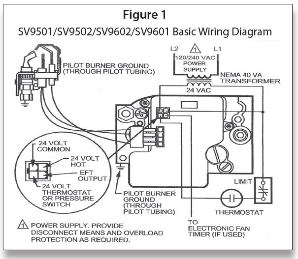
One of the first things to know in order to properly troubleshoot a system is the sequence of operation. If you do not know how it is supposed to work, then how will you be able to fix it? In this segment we are going to look at a Forced Warm Air System.
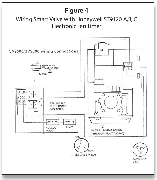
This particular system is composed of a Honeywell SmartValve™ Generation I SV9500/9600 with a Honeywell Electronic Fan Timer ST9120A, B or C. Using the diagram shown in Figure 2 we will walk through a sequence of operation on this system.
It is interesting to note that modern systems all come with wiring diagrams, both connection diagrams and ladder diagrams, trouble trees, and in some cases we even have diagnostic LEDs to help us find the problems. These, along with a written-out sequence of operation, should make our jobs easier.
The diagram shown in Figure 2 is for a Forced Warm Air System; it shows some air conditioning components, which will not be covered in this instruction.
Sequence of operation
The sequence of operation is as follows:
1. There is 120 VAC fed to terminal S1 on EFT—Neutral wire to N1.
2. 120 VAC is fed from terminal S2 to the primary of a 24 VAC transformer—N4 is neutral. In order to be able to more easily follow this sequence, Figure 3 will illustrate pin numbers and shape of pins for the ST9120.
3. The secondary of transformer goes to X (hot) C (common) Note: on some EFTs, there is a feed from X–4 and C–2 on 6-pin connector.
4. There is an un-interrupted 24 VAC from X and C to SmartValve™ or from pin 4–24 V AC (Hot) to Pin 2–24VAC (common).
5. When thermostat calls for heat R to W
a. 120 VAC is fed out of DI (draft inducer) to combustion blower neutral to N3.
b. The combustion air blower will cause the pressure switch to make COM to NO.
c. 24 VAC out from X to Pin 1 on 6-pin connector.
d. Pin 1 through limit and roll out switch to pin 6 to R (thermostat) through printed circuit board.
e. R to thermostat back to W to pin 3 on 6-pin connector.
f. Pin 3 to pressure switch and auxiliary limit to thermostat terminal on SmartValve™.
6. SmartValve™ is powered 24 VAC to the igniter, igniter glows and lights pilot gas—pilot proves back on clear (or sometimes black) wire a .3 microamp signal or greater. The main valve opens and lights from pilot burner. At this time, a data signal is superimposed on a voltage signal and fed to the EFT pin 5 on 6-pin connector.
7. Different ST9120 EFT boards will have dip switches for fan delay on and fan delay off (three dip switches) or just fan off delay (two dip switches). The 2-dip switch model has a fixed fan on time of 30 seconds. The 3-dip switch model has fan on times of 30 or 60 seconds. The off time on both can be 60, 100, 140 or 180 seconds. The data signal back to the EFT will trigger the fan on timing.
8. The fan comes on and runs until the thermostat is satisfied. Depending on the connection at the motor the fan will run on low, medium low, medium high or high speed. For heating, the HEAT terminal on EFT should be connected to low on motor and back to N2 on EFT. (Note: M1 and M2 on EFT are for unused motor leads).
9. When the thermostat is satisfied, the circuit to EFT is broken, the SmartValve™ shuts down and the fan-off delay starts (based on dip switch settings).
10. Fan shuts off—waiting for next call for heat. This completes the sequence of operation. It is the first step in troubleshooting and must be understood in order to further grasp how the system operates.
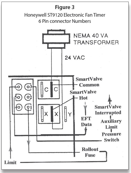
Figure 4 shows how the sequence takes place coming off the ST9120 control. It should be noted that the Auxiliary Limit is often difficult to find on Forced Warm Air Systems. It is sometimes located on the outlet side of the unit. Its purpose is to protect the heat exchanger from becoming damaged by excessive temperature. The whole idea of higher efficiency systems is to hold as much heat in the unit versus losing heat up the vent. This is why the system fan has to come on so soon.
Educational opportunities
Finally, I love to teach and would love to have you join us for some training. We conduct seminars on the following topics and many others:
One-Day Course:
• Powerpile Systems
Three-Day Course:
• Combustion Testing Design Gas Equipment
• Conversion Burners
Four-Day Course Designed for Your Specific Need:
• Modulating/Condensing Boilers
Five-Day Course:
• Fundamentals of Gas
• Circuitry & Troubleshooting
• Hydronic Controls
• Electric Ignition Systems
• Advanced Electric Ignition Systems
For more information, Tel: 401-437-0557; E-mail: timmcelwain@gastcri.com or write to: Gas Appliance Service Training & Consulting, 42 Village Dr., Riverside, RI 02915. ICM
Part V, from the Mar/Apr 2022 Indoor Comfort
Parts I & II, from the Jul/Aug and Sep/Oct 2021 Indoor Comfort can be found here.
Part III, from the Nov/Dec 2021 Indoor Comfort can be found here.
Part IV, from the Jan/Feb 2022 Indoor Comfort can be found here.
As we look into some more modern systems and what specific problems they present, it is important to understand the basic fundamentals associated with these systems. Most of our modern heating equipment in some way or another involves electronics and the use of flame rectification as a safety and flame-proving system.
It doesn’t matter if it is a forced warm air furnace or a forced hot water boiler—the same basic system is used to perform safe ignition followed by consistent operation throughout the entire call for heat.
There are, however, different ways the system is applied from intermittent pilot application to direct spark ignition and including hot surface ignition. Each has its own distinct advantages and problems. We’ll now attempt to resolve those burner problems related to these systems, as well as offer corrections and diagnostics.
We will start with the basics and then continue to operation, typical problems, diagnosis, troubleshooting procedures and a final solution to a particular problem. It’s easy to jump to conclusions with these systems and just change parts to hopefully solve a problem. That is, however, time-consuming and costly.
I invite you to visit our new Facebook page Timmie’s Tips on Gas. I look forward to seeing you there.
This article covers some of the tools and aids available to troubleshoot SmartValve™ Generation I and II. Most of these aids can be purchased at your local heating supply stores with the part numbers mentioned here.
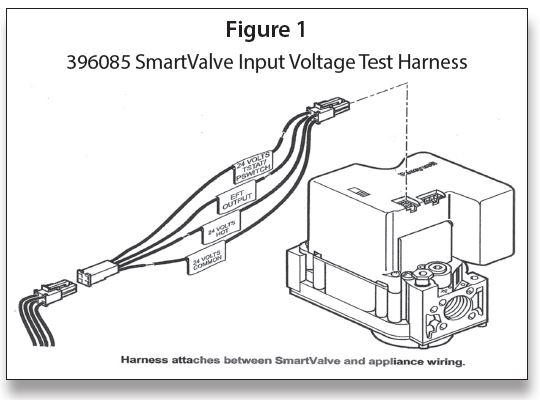
SmartValve™ Input Voltage Test Harness (Part # 396085)
The 396085 SmartValve™ Input Voltage Test Harness shown in Figure 1 helps a user to confirm proper appliance control string operation in the field. When installed between the appliance harness and the SmartValve™, the 396085 Test Harness is used to connect a voltmeter to the SmartValve™. This allows the user to monitor the input signals to the SmartValve™ controls. Proper SmartValve™ operation requires the appliance control string to supply the needed input signals during a call for heat.
Test Procedure
Note: Leave SmartValve™ switch in ON position.
1. Turn off gas supply at the appliance shut-off valve.
2. Make sure appliance is powered.
3. Lower the temperature controller setting to make sure there is no call for heat.
4. Disconnect the appliance wiring harness (2×2 connector) from the SmartValve™.
5. Connect the test harness between the appliance wiring and the SmartValve™, as shown in Figure 1. Make sure the keyed connectors lock into place.
6. Measure the voltage between the 24-volt hot (white label) lead and the 24-volt common (gray label) lead on the test harness. If the voltage is less than 20 volts or more than 28 volts, check the appliance power supply and the system transformer for proper functioning. Note: If an appliance is wired so the 24-volt hot lead is controlled with the 24-volt TSTAT/ PSWITCH (yellow label) lead, there is no voltage between the 24-volt hot lead and the 24-volt common lead in Step 6.
7. Disconnect the voltmeter or multimeter from the 24-volt hot lead.
8. Connect the voltmeter or multimeter to the 24-volt TSTAT/PSWITCH (yellow label) lead.
9. Set the temperature controller so it calls for heat.
10. Make sure the meter displays nominal 24 volts while the light-off sequence progresses, and the reading is steady with the element glowing. Note: Thevoltage in Steps 10 and 11 should be between 19 VAC and 26 VAC with the Q3450 element glowing and the gas turned off. If the measured voltage is outside the acceptable range, analyze the appliance control string, input voltage supply and the transformer to identify the problem. Correct the problem and retest the appliance.
11. If the voltage is within the acceptable range, turn off the call for heat and make sure the measured voltage decreases to zero.
12. Disconnect the voltmeter or multimeter leads from the test harness.
13. Connect the leads to the EFT output (green label) lead and the 24-volt common lead.
14. Turn on the gas supply.
15. Initiate a new call for heat.
16. When the appliance main burner lights, measure the voltage between the EFT output lead and the 24-volt common lead. This is a logic signal and can range from 15 VAC through 28 VAC.
17. Test is complete. Turn off appliance call for heat.
18. Disconnect the test harness from the SmartValve™.
19. Connect the appliance wiring harness to the SmartValve™.
20. Turn on call for heat and make sure the appliance works properly.
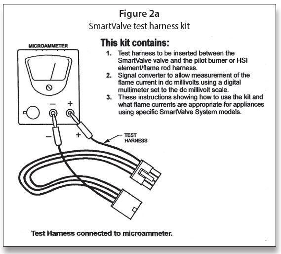
Measuring SmartValve™ System Flame Current (Part # 395466)
This Honeywell SmartValve™ System flame current kitallows the trained service technician to determine flame current levels generated in a SmartValve™ System equipped gas-fired appliance. Knowing the strength and stability of the flame current signal being generated by the appliance can help the technician diagnose intermittent appliance operation and predict future appliance problems.
Many factors influence the flame current being generated by an installed appliance. The ignition control generates an AC voltage potential between the flame sense rod and the burner ground area. When flame is present, the geometry of the flame rod/ground area (1–4) combines with the voltage potential present to generate a low-level (microamperes) rectified DC current. The ignition control monitors this current to determine if sufficient flame is present to operate the appliance. If the appliance does not generate sufficient flame current, the main burner will not operate and the appliance will not deliver heat. If the flame current generated is unstable and fluctuates, there is high likelihood for inconsistent appliance operation. The service technician must insure that the appliance generates a strong and steady flame current well above the minimum threshold to assure reliable appliance operation.
Honeywell SmartValve™ Systems are available with two types of ignition sequences:
• Intermittent pilot models use a low voltage hot surface ignition (HSI) element to light the pilot gas; main burner gas flows and the main burner lights when the pilot flame is sensed.
• Direct hot surface ignition models use a 120-volt hot surface ignition element to directly light main burner gas; if the main flame is sensed at the end of the trial for ignition, the main burner continues to fire.
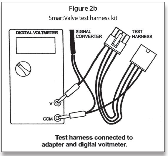
The kit shown in Figure 2a and Figure 2b is suitable to measure flame current on both types of systems. Select the proper procedure, below, based on the type of SmartValve™ System in the appliance. Equipment needed:
1. Analog DC microammeter, such as Honeywell W136, which has a 0 to 25 microampere range, or
2. Digital volt-ohmmeter with a DC millivolt scale
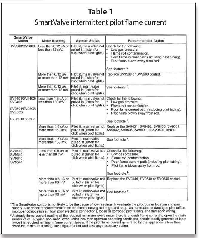
Measuring Pilot Burner Flame Current On Intermittent Pilot SmartValve™ Systems
Intermittent Pilot SmartValve™ Systems include: SV9401, SV9402, SV9403, SV9501, SV9502, SV9503, SV9601, SV9602, SV9440, SV9450, SV9541 and SV9640.
When testing with this kit in Figures 2a and 2b:
1. Read these instructions carefully. Failure to follow the instructions can damage the product or cause hazardous conditions.
2. Check the ratings given in the instructions and on the product to make sure the product is suitable for your application.
3. Troubleshooter must be a trained, experienced service technician.
4. After completing the measurements, use the appliance instructions to check the product operation.
 IMPORTANT: Accurate flame current measurement can be performed only with the pilot flame lit and the main flame not lit. When measuring with this kit, the appliance main burner orifices should be temporarily plugged while measuring system flame current. Be sure to remove the temporary plug and check the appliance for proper operation after completing the test.
Direct Measurement
Note: Direct measurement requires an analog DC micro-ammeter capable of reading to 0.01-microampere accuracy. No signal converter required.
1. Disconnect all power to the appliance.
2. Connect the test harness between the valve control and the pilot burner.
a. Insert the banana plug connected to the valve side of the test harness into the positive (+) jack on the DC microammeter as shown in Figure 2a.
b. Insert the other banana plug connected to the pilot burner side of the test harness into the negative (-) jack on the DC micro-ammeter as shown in
Figure 2a.
3. Reconnect power to the appliance.
4. Generate a call for heat.
5. Make sure the pilot flame lights and the main burner does not light.
6. After the pilot flame is on for ten seconds, read the DC micro-ammeter. The readings must be steady.
7. Take the action recommended in Table 1.
Millivolt Measurement
Note: Millivolt measurement requires a digital voltmeter capable of reading DC millivolts. Use the signal converter included with this kit. See Figure 2b.
1. Disconnect all power to the appliance.
2. Connect the signal converter to the voltmeter.
3. Set the voltmeter to read DC millivolts.
Note: The signal converter is not polarity sensitive.
4. Connect the test harness between the valve control and the pilot burner.
a. Insert the valve side of the test harness through the female end of the signal converter connector and into the positive (+) jack of the digital voltmeter, as shown in Figure 2b.
b. Insert the pilot burner side of the test harness through the female end of the signal converter connector and into the negative (-) jack of the digital voltmeter, as also shown in Figure 2b.
5. Reconnect power to the appliance.
6. Generate a call for heat.
7. Make sure the pilot flame lights and the main burner does not light.
8. After the pilot flame is on for 10 seconds, read the digital voltmeter. The readings must be steady.
9. Take the action recommended in Table 1.
The SmartValve™ Input Voltage Test Harness available for troubleshooting these systems is Honeywell Part # 396085. The Measuring SmartValve™ System Flame Current (Part # 395466) is the kit to measure Microamps.
There will be more on troubleshooting SmartValve™ in the next article.
Finally, I love to teach and would love to have you join us for some training. We conduct seminars on the following topics and many others:
One-Day Course:
• Powerpile Systems
Three-Day Course:
• Combustion Testing Design Gas Equipment
• Conversion Burners
Four-Day Course Designed for Your Specific Need:
• Modulating/Condensing Boilers
Five-Day Course:
• Fundamentals of Gas
• Circuitry and Troubleshooting
• Hydronic Controls
• Electric Ignition Systems
• Advanced Electric Ignition Systems
For more information, Tel: 401-437-0557; E-mail: timmcelwain@gastcri.com or write to: Gas Appliance Service Training & Consulting, 42 Village Dr., Riverside, RI 02915. ICM
Part IV, from the Jan/Feb 2022 Indoor Comfort
Parts I & II, from the Jul/Aug and Sep/Oct 2021 Indoor Comfort can be found here.
Part III, from the Nov/Dec 2021 Indoor Comfort can be found here.
As we look into some more modern systems and what specific problems they present, it is important to understand the basic fundamentals associated with these systems. Most of our modern heating equipment in some way or another involves electronics and the use of flame rectification as a safety and flame-proving system.
It doesn’t matter if it is a forced warm air furnace or a forced hot water boiler—the same basic system is used to perform safe ignition followed by consistent operation throughout the entire call for heat.
There are, however, different ways the system is applied from intermittent pilot application to direct spark ignition and including hot surface ignition. Each has its own distinct advantages and problems. We’ll now attempt to resolve those burner problems related to these systems, as well as offer corrections and diagnostics.
We will start with the basics and then continue to operation, typical problems, diagnosis, troubleshooting procedures and a final solution to a particular problem. It’s easy to jump to conclusions with these systems and just change parts to hopefully solve a problem. That is, however, time-consuming and costly.
I invite you to visit our new Facebook page I look forward to seeing you there.
SmartValve™ Generation I & II Troubleshooting
The troubleshooting of the SmartValve™ itself is fairly simple. We will, however, incorporate the valve into some actual systems. We will address a forced warm air system first. The low voltage portion of a warm air system is shown in Figure 1 with an EFT (Electronic Fan Timer). The line voltage portion of the system is shown in Figure 2.
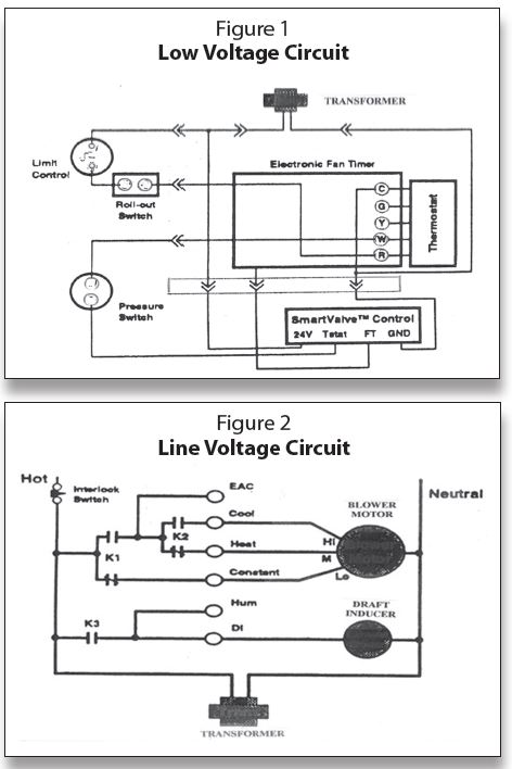
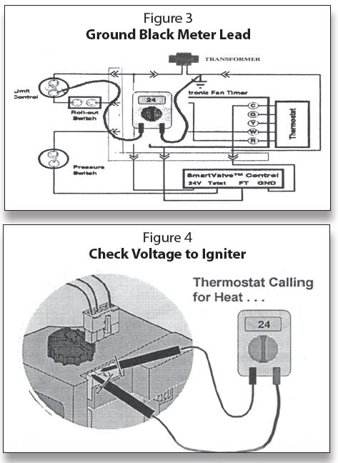
Figure 3 illustrates a method of using a multimeter. That is grounding one lead of the meter to the common side of the transformer, the “C” terminal, and leaving it there. The other lead is used to go from control to control to check for voltage.
The best place to start troubleshooting is at the output to the igniter shown in Figure 4. With the thermostat calling or not with power applied, you should have 24 volts at that location. If there are 24 volts there you know the transformer is good, the 120 volts are good. If you have problems, then it is probably in the igniter sensor. One more important time-saver is—when troubleshooting with a combustion air blower on the equipment—if the blower runs, the 24 volts and 120 volts are okay. Obviously if there is a problem with 120 or 24, the combustion air blower would not run. If you have 24 volts at the output terminals and the system does not light, then the problem is with the igniter itself.
At the same time, with the igniter sensor disconnected, switch your meter over to the ohms scale and check the igniter resistance by going across the two terminals connected to the blue wires as illustrated in Figure 5. A new igniter is usually 2–4 ohms resistance. Up to 10 ohms is okay; anything over 10-ohm will require igniter replacement.
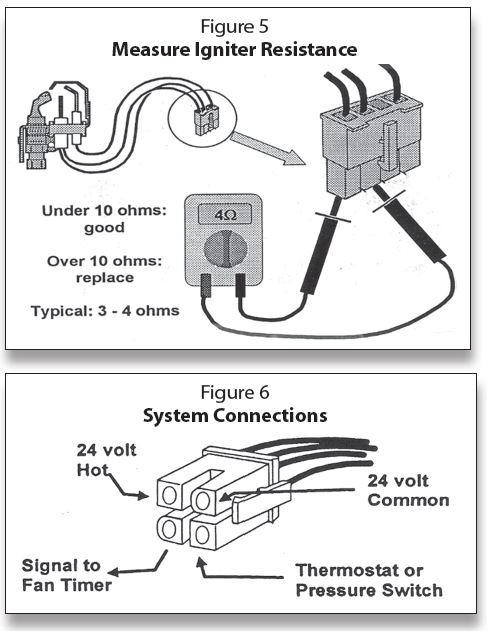
If you do not have 24 volts at the output to the igniter, then check power to the valve at the control plug as shown in Figure 6:
Electrical connections:
• 24 volt common goes to the grounded side of the transformer secondary—“C” on the transformer.
• 24 volt hot goes to the hot side of the transformer secondary—“R” on the transformer.
• Thermostat terminal brings the call for heat signal from the thermostat or pressure switch, depending on the type of equipment and control circuit.
• The thermostat does not carry the igniter current.
• Anticipator setting is .3 amps safely within the adjustment range of all electromechanical thermostats.
The Electronic Fan Timer (EFT) signal is on whenever the main valve is open and:
• Tells when to start timing the Fan-On delay.
• Tells when to start timing the Fan-Off delay.
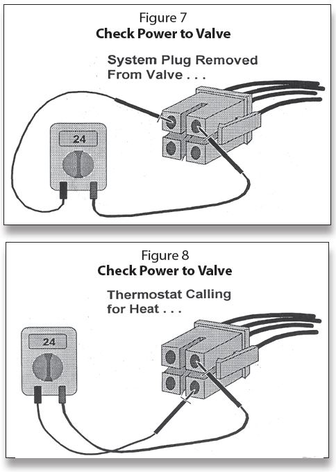
In checking the control plug, as shown in Figure 7, you should have 24 volts at all times when the power is on. This is the uninterrupted voltage. If 24 volts are not measured here, check the transformer. If you have 24 volts here, check the two right-hand terminals as shown in Figure 8. If there are not 24 volts on the terminals, one of the controls is open in either the thermostat, limits or even the pressure switch.
It is also a good idea to make sure that there is no appreciable loss of voltage in the conditions of under load (thermostat calling) shown in Figure 9 and no load (no call for heat) shown in Figure 10. Whether load or no load, voltage should remain between 19 to 28 volts.
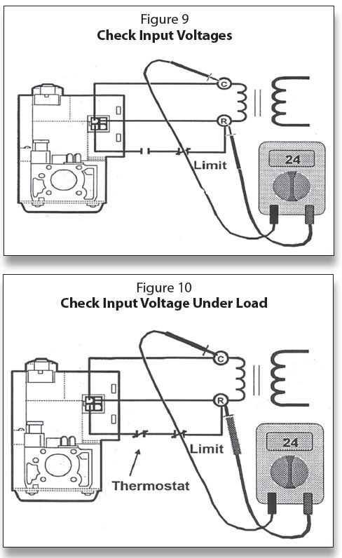
The SmartValve™ system needs an uninterrupted 24 volts to run the electronics in the valve and then a 24-volt signal through the thermostat circuit on a call for heat. By using the correct size transformer, a stable voltage should be able to be maintained. When the SmartValve™ has energized the igniter, check the voltage; if the voltage holds up under that load, it should remain a stable 24 volts. The more it deviates from the 24 volts, the more the problem is likely to be the transformer, or perhaps the line voltage to the transformer. It could also be an indication that the valve is increasing appreciably in resistance, thereby demanding greater current flow and causing the voltage to decrease.
Microamps
The ability to prove the flame and safely light the main burner is accomplished by the process of flame rectification. The Generation I electronic systems produce a 24-volt superimposed voltage from within the valve electronics. This signal is passed through the flame and produces a DC microamp signal of 0.3μ amp minimum. This voltage determines the intensity of the microamp signal. If the system is not working correctly, this check will be the first step in proving if the problem is microamps or the valve itself. For readings:
• The Generation I signal is 24 volts
• The Generation II signal is 80+ volts
See the Generation I and II signals in Figure 12. These voltages can be checked. With the igniter plugged into the gas valve (the illustration in Figure 11 shows it unplugged; it should be plugged in), ground one lead of the multimeter to ground (the gas valve is a good ground) while the other lead is inserted at the back side of the pilot harness on the black or clear wire microamp wire. Note: a paper clip fits nicely into the back of the harness for this reading.
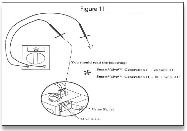
If the readings are less than required, then replace the SmartValve™. Note: microamp readings cannot be obtained unless you have a special test harness, which is discussed later in this article. The minimum microamps for each generation is shown in Figure 12.
Flame proving circuit:
• About 0.3 microamps D.C. for the first generation SmartValve™. It uses 24 volts in the flame-sensing circuit and so the flame current is relatively small.
In addition to voltage checks, another indicator is the status of the igniter. This can be in the place of microamp readings
• If the igniter is off and the pilot is lit, but the main valve will not open, then the problem is not in the sensing circuit (Microamps) but in the main valve. If the igniter is off, you know the flame has been detected.
• If the pilot is lit and the igniter is still glowing, but the main valve will not open, then the problem is in the sensing circuit.
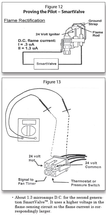
On Warm Air Systems, there will be an output signal available from the SmartValve™ to trigger the Electronic Fan Timer (EFT). It is the fourth terminal located on the lower left-hand side—a backwards “D” shape.
The signal is on whenever the main valve is open and is a DATA signal to the microprocessor on the circuit board. It:
• Tells when to start timing the Fan-On delay
• Tells when to start timing the Fan-Off delay
The output from this terminal on the connector can be measured and should be between 15 to 28 volts AC. This can be measured by placing a paper clip, attached to the alligator clip on the meter lead, and inserting it into the back of the control plug as shown in Figure 13 (the plug is shown detached; it should actually be plugged into the valve). It should be placed between Common and the EFT output terminal. You could also obtain this reading by using the Input Voltage Test Harness.
There is a SmartValve™ Input Voltage Test Harness available for troubleshooting these systems. It is Honeywell Part No. 396085. There is also a kit to measure Microamps. It is Measuring SmartValve™ System Flame Current, Part No. 395466.
We will discuss troubleshooting the Smart-Valve™ in an upcoming issue. ICM
Timmie M. McElwain is President of Gas Appliance Service, which provides training for those servicing gas combustion equipment. He is a certified instructor and test proctor for the Propane Gas Association in their CETP program.
Part III, from the Nov/Dec 2021 Indoor Comfort
Parts I & II, from the Jul/Aug and Sep/Oct 2021 Indoor Comfort can be found here.
As we look into some more modern systems and what specific problems they present, it is important to understand the basic fundamentals associated with these systems. Most of our modern heating equipment in some way or another involves electronics and the use of flame rectification as a safety and flame-proving system.
It doesn’t matter if it is a forced warm air furnace or a forced hot water boiler—the same basic system is used to perform safe ignition followed by consistent operation throughout the entire call for heat.
There are, however, different ways the system is applied from intermittent pilot application to direct spark ignition and including hot surface ignition. Each has its own distinct advantages and problems. We’ll now attempt to resolve those burner problems related to these systems, as well as offer corrections and diagnostics.
We will start with the basics and then continue to operation, typical problems, diagnosis, troubleshooting procedures and a final solution to your particular problem. It’s easy to jump to conclusions with these systems and just change parts to hopefully solve a problem. That is, however, time-consuming and costly.
I invite you to visit our new Facebook page Timmie’s Tips on Gas. I look forward to seeing you there.
SmartValve™ Typical Wiring
The wiring for the SmartValve™ is fairly simple; it is not much more complicated than wiring for a standing pilot 24-volt system. Figure 1 shows an example of the typical wiring required. It needs a constant, uninterrupted 24 volts to run the electronics in the valve and a 24-volt signal that comes through the thermostat circuit and limits.
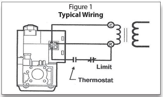
A 40 VA transformer, which is National Electrical Manufacturers Association (NEMA) rated Class II Standard DC20-92, is required for the SV9500 series and a 50 VA for the SV9600 Series. The igniter draws about 1.25 amps and the total current required is about 1.5 amps. Figure 2 shows the capacity and versatility of a NEMArated transformer.
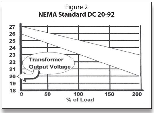
NEMA standards for transformers specify how well the transformer must hold its output voltage under load conditions, as illustrated in Figure 2:
Voltage regulation:
• Nominal rating = 24 volts
• Open circuit = between 26 and 27 (no more than 27 volts)
• Full load = 23 to 25 Volts
• Twice full load = 20 to 23 Volts
SmartValve™ power requirements:
• Valve + igniter + thermostat + fan timer = 1.55 to 1.87 amps
37.2 to 44.9 VA
• Load on 50 VA transformer =
• 40 VA transformer load = 93 to 112%
A lower quality transformer is likely to have the voltage drop off much more rapidly so it will have a higher open circuit voltage. It will also have a lower voltage at 200% of rated load to get to 24 volts at full load.
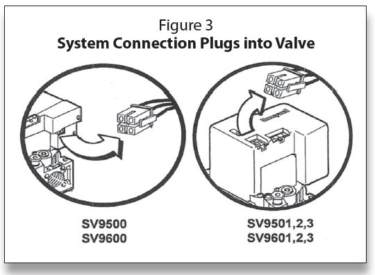
Making connections
One of the changes made from Generation I to II was moving the system connector plug from the side to the top of the control, as illustrated in Figure 3. This plug can be unplugged for service and checkout when necessary; we will expand on troubleshooting in an upcoming column.
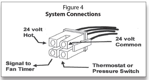
In Figure 4, we have an expanded view of the system connector. Looking at the connector with the clip to the right, the upper left square terminal is 24 volts hot (the “R” terminal from the transformer). To the right is the backwards “D” shaped plug, which is the common terminal (the “C” terminal from the transformer).
The lower right square terminal is the interrupted 24 volts through the thermostat (the anticipator setting is 0.3 amps) and limit controls. The lower left backwards “D” terminal is the EFT (Electronic Fan Timer) output terminal. This is a microprocessor “DATA” signal superimposed on an AC voltage feed to the electronic fan timer to determine the start of the fan on delay timing cycle. It also tells when to start timing the fan-off delay. We will discuss more of this troubleshooting, connector testing and the use of a test harness in a following column.
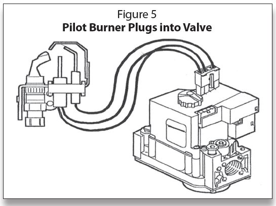
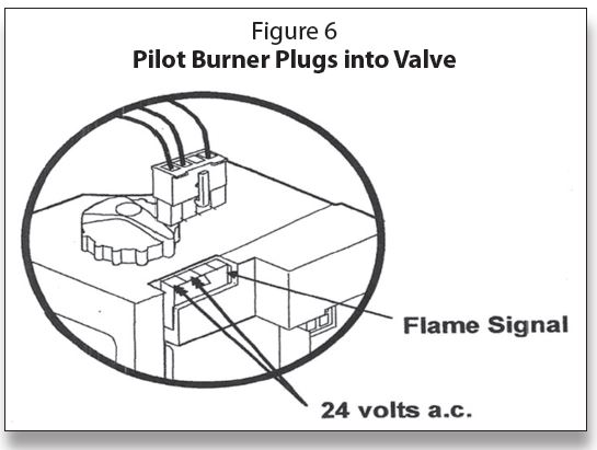
The other plug on top of the SmartValve™ is for the pilot burner, as shown in Figure 5. The pilot connections are 24 volts to the igniter on the two blue wires. The clear wire, or in some cases the black wire, is for the microamp flame signal to get back to the electronics in the valve, as illustrated in Figure 6. This pilot plug-in becomes an excellent point to start troubleshooting on this system; we will discuss more in an upcoming column.
Part numbers
Some miscellaneous information on SmartValve™ Generation I and II concerns natural/liquid propane (LP) conversion and part numbers for orifices and kits for accomplishing conversion. These are shown in Figure 7.
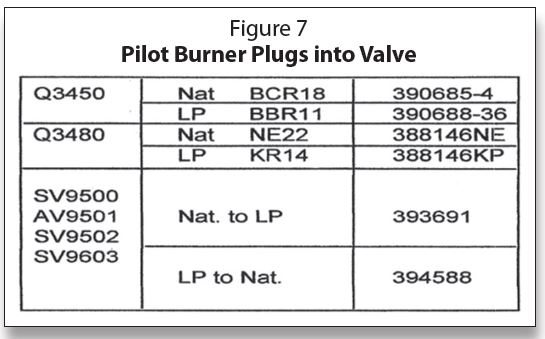
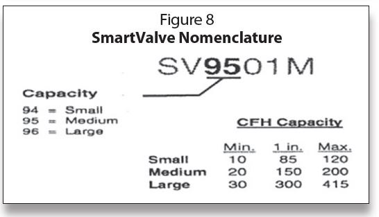
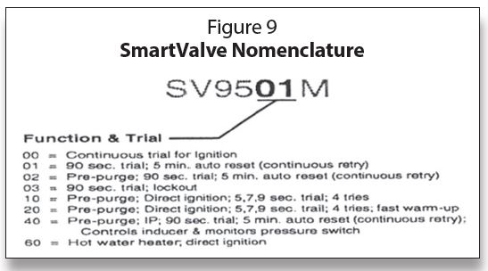
Figure 8 and Figure 9 break down the nomenclature for Generation I and II along with Generation III controls. It also includes the SmartValve™ water heater control numbers.
A list of Universal SmartValve service part replacement numbers that are still being produced, as well as obsolete numbers, can be found in the Tradeline Catalog Cross Reference.
Electronic Fan Timer Output Terminal
Back in Figure 4, we mentioned the “lower left backward D” shaped terminal. This is the Electronic Fan Timer (EFT) output terminal. This is a microprocessor “DATA” signal superimposed on an AC voltage feed to the electronic fan timer to determine the start of the fan on a delayed timing cycle. It also tells when to start timing the fan-off delay. To expand on this, “DATA” is a signal that rides “piggy back” on the AC signal. It carries electronic information to affect the operation of the timer. We will cover troubleshooting SmartValve systems in the next issue of ICM. ICM
Timmie M. McElwain is President of Gas Appliance Service, which provides training for those servicing gas combustion equipment.
He is a certified instructor and test proctor for the Propane Gas Association in their CETP program.