As we look into some more modern systems and what specific problems they present, it is important to understand the basic fundamentals associated with these systems. Most of our modern heating equipment in some way or another involves electronics, and with the electronics, the use of flame rectification as a safety and flame-proving system.
It does not matter if it is a forced warm air furnace or a forced hot water boiler—the same basic system is used to perform safe ignition followed by consistent operation throughout the entire call for heat.
There are, however, different ways the system is applied from intermittent pilot application to direct spark ignition and including hot surface ignition. Each has its own distinct advantages and problems. In this next series, we’ll attempt to resolve those burner problems related to these systems as well as offer corrections and diagnostics.
We will start with the basics and continue to operation, typical problems, diagnosis, troubleshooting procedures and hopefully a final solution to your particular problem. It’s easy to jump to conclusions with these systems and just change parts to hopefully solve the problem. That is, however, time consuming and costly.
I invite you to visit our new Facebook page Timmie’s Tips on Gas, it is located here. I look forward to seeing you there.
The Honeywell Smart Valve story
In this article, we are going to cover the Honeywell Smart Valve systems and discuss Generation I and Generation II. Generation I is obsolete, but controls from that series may still be in the field.
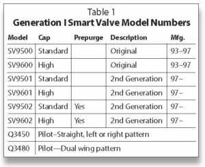
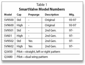
Smart Valve is the name Honeywell has given a unique ignition system developed in 1993. The Smart Valve combines all the best features of intermittent pilot ignition and hot surface ignition. It utilizes a pilot to light the main burner. It uses a glowing 24-Volt igniter to light the pilot light instead of a spark. There have been two Smart Valve systems. The first generation was manufactured from 1993–1997. Generation I included SV 9500, SV9501, 02 (0.5″ x 0.5″ pipe and 200,000 BTUs) and SV9600, SV9601, 02 (0.75″ x 0.75″ pipe and 415,000 BTUs). The new generation is still in production at the present time.
System controls & application
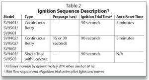
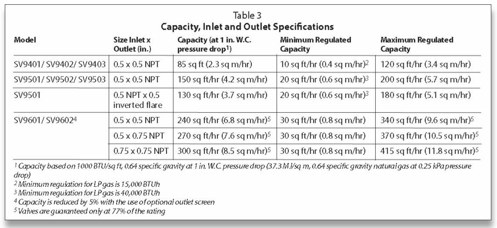
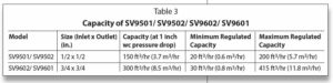
The SV9401/ SV9402/ SV9403, SV9501/ SV9502/SV9503 and SV9601/ SV9602 SmartValve System Controls combine gas flow control and electronic intermittent pilot sequencing functions into a single unit. This product family offers several different intermittent pilot sequences for a wide range of applications. See Table 2 for specific sequences available. The Q3450 or Q3480 intermittent pilot hardware provides low voltage ignition, flame sensor and pilot burner. This system is suitable for application in a wide range of gas-fired appliances including furnaces, rooftop furnaces, boilers, unit heaters, infrared heaters, space heaters, water heaters, decorative appliances and commercial cooking units. The specific application of the SmartValve System is the responsibility of the appliance manufacturer. See Table 3 for gas capacity and thread sizes.
The Tradeline SV9501 and SV9502 SmartValve models are replacement controls only for the SV9500, SV9501 and SV9502 models. Do not use these controls to replace other types of intermittent pilot or direct ignition controls. Do not use other controls to replace SmartValve models; the controls might fit, but the gas flow control functions might not be compatible with the appliance.
The Tradeline SV9602 SmartValve models are replacement controls only for the SV9500P, SV9501 P, SV9502P, SV9600P and SV9601 P models. The SV9602 is a prepurge, step-opening model.
1. Prepurge is normally 30 seconds.
2. The step-opening function provides a timed step outlet pressure at the start of each heating cycle to allow main burner ignition at reduced outlet pressure.
3. Reducer bushings are provided with the SV9602 and SV9601 models to adapt to smaller pipe sizes.
4. Ignition system controls with standard opening regulators (SV9501M, SV9502M and SV9601M) or slow opening regulators (SV9501 and SV9502H) can be converted between natural gas and liquefied petroleum (LP) gas.
5. Ignition system controls with step-opening regulators (P suffix) cannot be converted between gases.
Pilot burners
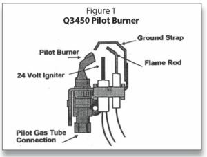
The first difference you see is the pilot burner—a standard Honeywell burner similar to the Q314. What is unique is the ignition source for the pilot:
• Small igniter in front of the pilot
• Powered by 24 Volts
• Glows red hot on a call for heat to light the pilot.
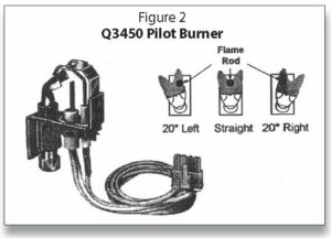
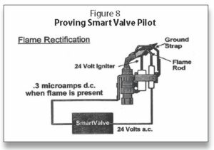
The igniter is made of silicon nitride, which is similar to the material used for hot surface igniters. It is, however, stronger and is well-protected by the pilot burner and ground strap so that it does not break unless it receives unusual abuse. The igniter has a positive coefficient with a relatively low resistance when cool. Therefore, the initial current flow makes it heat up very fast. The pilot usually lights in a few seconds. The flame rod is positioned to “prove” the pilot. Flame rectification is used to prove the pilot flame is burning. When the flame is detected the igniter is turned off. The main valve opens. Flame rectification provides fast, sensitive flame detection.
The igniter flame rod assembly is replaceable without having to replace the entire pilot, which is a great advantage over intermittent pilot systems. The original pilot and harness that plugs into the valve (Part No. Q3400A-1024) was an unshielded version. A shielded version (Part No. Q3400A-1115) was released due to problems with pinching the cables and getting a feed over of 24 Volts on the microamp wire. The blue wires on the harness are for 24 Volts to get the igniter to glow. The first versions had a clear wire, which was for the microamp signal back to the electronics on the valve. It was later changed to a black wire. The Generation I valves used 24 Volts as a superimposed signal and they had a minimum microamp signal of .3 microamps. Generation II uses 80 + Volts to create a minimum signal of 1.3 microamps.
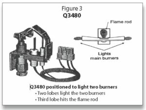
The pilots are the Q3450 (Figure 1 and Figure 2), which is a lower input pilot, and the Q3480 (Figure 3) version, which has a little higher input.
The Smart Valve is a dual valve (redundant) valve based on the VR8200 and VR8300 series of gas valves. The dual valve feature guards against the possibility of a passing gas valve. The capacity goes all the way up to 415 cubic feet per hour and has a 1″ W.C. pressure drop at 300 CFH.
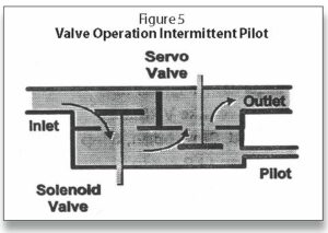
Figure 5 shows that the first valve is a solenoid valve, which opens upward and is actually the PV (pilot valve). It is designed in such a way that if pressure in excess of 14″ W.C. is applied to the valve, it may not open. This is a safety feature to prevent over-pressure and possible damage to the diaphragm valve. The second valve is the servo valve (a diaphragm valve controlled by the servo regulator); it is typically the MV (main valve). The second servo valve will not be powered until the flame is proven by rectification.
There are various models available to manufacturers:
• Standard open (M model)
• Slow open (H model)
• Step open (P model)
The M and P models are rated for -40°F so they can be used on rooftop units or other unheated spaces. Replacements for many models can be found in the Honeywell Tradeline catalog or at customer.honeywell.com.
The valves can be used with natural or LP gases. The exception is the P model (step opening), which can’t be converted. There are conversion kits available:
• Natural to LP 393691
• LP to Natural 394588
There are also pilot orifices available for the Q3450 pilot:
• Natural BCR18 (.018)
• LP BBR 11 (.011)
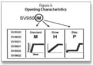
Figure 6 illustrates the different opening characteristics of SmartValve Standard open valve:
• Fast open
• Reaches full rate in 1–2 seconds, depending on capacity
• On some applications, particularly low firing rates, there is little variation in regulation for a half second when it first turns on
Slow open valve
• Takes about 4–5 seconds to get fully open
• Under maximum capacity, it may even take 9–10 seconds to get fully open
• Again, for service, replace with slow open
Step open
• Valve opens to some fixed (non-adjustable) low rate for light-off, and after 10 seconds, goes to full rate
• For service work, replace with step opening only as there may be ignition problems with any other opening characteristic
• Equipment manufacturers chose step open (at higher cost) for a reason
• Usually used to make light-off smoother or to cure light-off problems
When the Smart Valve receives a call for heat, there is an immediate surge of current due to the low resistance through the igniter (low cold resistance). Silicon nitride has a positive temperature coefficient. Line voltage igniters have a negative temperature coefficient. The hot resistance is high. There is a 22.5 Volt drop across the igniter and a 1.5 Volt drop across the pilot valve relay coil. The pilot valve relay coil is immediately energized, pulling in the pilot valve. On the original Generation I Smart Valve there was continuous trail for ignition—the igniter came on and stayed on until the system lit off. Generation II has continuous retry with a 90-second trial for ignition followed by a 5-minute wait period if ignition does not take place.
During the 90-second attempt at ignition, the igniter will be on for 30 seconds, then shut off for 25 seconds, then back on for 30 seconds. This is to keep from overheating the pilot relay and to extend the life of the igniter.
SV9501 (Generation II) features
The new features of Generation II of the Smart Valve include:
• Meeting new Z21.20 requirements
• Switch provides manual shutoff
• Soft element warm up
For direct replacement for the SV9500, or Generation I, you should be aware of the following:

• Same package shape and size
• Same Q3450 pilot burner
• Identical connectors (power connector on top)
The steps for the Call for Heat are as follows:
• Start check (three seconds)
• Trial for ignition (90 seconds)
• Pilot valve open
• HSI on (30 seconds)
• HSI off (25 seconds)
• HSI on (30 seconds)
• Pilot valve closed /HSI off
• Retry delay (five minutes)
• Trial for ignition
• Retry delay
• Cycle continues until pilot lights/proves or the call for heat ends.
For theQ3450 & Q3480 pilots, the pilot igniter and flame rod assembly on both the Q3450 and the Q3480 need to be field replaced. Figure 7 gives an illustration for doing so. The directions are as follows:
Replace Igniter-Flame Rod Assembly
1. Turn off the furnace at the circuit breaker or fuse box.
2. Remove the spring clip, then the igniter-flame rod assembly from the pilot burner.
3. Disconnect the igniter-flame rod assembly keyed plug from the igniter connection on the SV9500/SV9600.
4. Remove the igniter-flame rod assembly from the furnace.
5. Install replacement igniter-flame rod assembly in the pilot burner and secure it with the spring clip.
6. Connect igniter-flame rod assembly keyed plug to igniter connection on the SV9500/SV9600.
7. Turn on power and set the thermostat to call for heat. The pilot should light and then the main burner should lights.
Note: Sensor tip must be in pilot flame.
Adjust Pilot Flame
The pilot flame should envelop approximately 3/8″ (10mm) of the sensor tip.
To adjust pilot flame:
1. Turn off system by setting thermostat below the temperature to call for heat.
2. Disconnect lead to MV terminal on SV9500/SV9600.
3. Light pilot by setting the thermostat to call for heat.
4. Remove pilot adjustment cover screw from gas control.
5. Turn inner pilot adjustment screw clockwise to decrease or counterclockwise to increase pilot flame.
6. Always replace pilot adjustment cover screw and tighten firmly after completing adjustment to assure proper operation.
The Generation I system used a 24 Volt signal for rectification and had a minimum microamp signal of 0.3 microamps, which proved to be somewhat of a problem as it was too low and caused some nuisance shut-downs. Generation II went to a minimum voltage signal of 80+ Volts with a minimum microamp signal of 1.3 microamps. The flame-proving circuit is illustrated in Figure 8. A complete discussion on flame rectification is in our manual Electric Ignition Systems Volume I.
Figures 9, 10, 11 and 12 illustrate the physical differences between Generation I and II. The SV9500 with the on/off knob easily distinguishes it from the Generation II SV9501 and SV9502. In addition to the Generation II having a switch, the control harness connector was moved from the side to the top. Also shown is the use of the flange kit, which makes for ease when replacing a valve, as the 9/64″ hex screws and the valve can be easily removed by using a wrench to unmake the threaded portion of the valves.
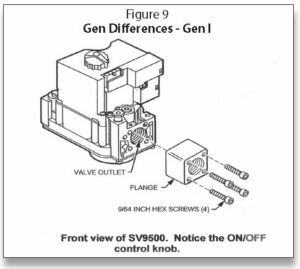
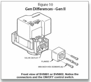
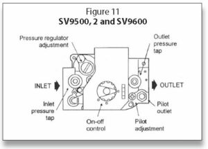
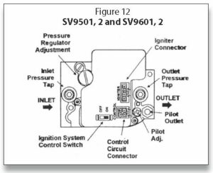
Figure 11 and Figure 12 also shows other typical characteristics of the valves, such as the pressure regulator adjustment, pilot outlet, inlet and outlet pressure taps for testing gas pressures with a manometer. The electrical connections visible on Generation II on top of the valve are the igniter connector and the control circuit connector.
Part 2 (From Indoor Comfort, Sep/Oct 2021)
Honeywell SmartValve
In this article, we continue our discussion of the Honeywell SmartValve. SmartValve is the name Honeywell gave a unique ignition system developed in 1993. The SmartValve combines all the best features of intermittent pilot ignition and hot surface ignition. It utilizes a pilot to light the main burner and a glowing 24-Volt igniter to light the pilot instead of a spark.
There have been two SmartValve systems. The first generation was manufactured from 1993–1997. The new generation is currently still in production. Generation I includes SV9500 and SV9501, 02 (1/2″ x 1/2″ pipe; 200,000 BTUs), as well as SV9600, SV9601, 02 (3/4″ x 3/4″ pipe; 415,000 BTUs).
Picking up where we left off in “The Gas Side—Honeywell Gas Valves: Part 1” in ICM’s July/August 2021 issue, here are directions for Standard Pressure Regulator (M Models), Slow Open (H Models, Step Open [P Models]):
1. Check the full rate manifold pressure listed on the appliance nameplate. The ignition system control outlet pressure must match the full rate pressure listed on the nameplate. Adjust the pressure if they do not match. Note: Slow opening (H models) and step opening (P models) may take several seconds to reach full flow rate. M models will take 2–3 seconds to reach full flow rate.
2. With the main burner On, check the ignition system control flow rate using the meter clocking method, or check the pressure using a manometer connected to the outlet pressure tap on the ignition system control.
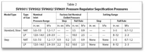
3. Adjust the pressure regulator to match the appliance rating if necessary. See Table 2 and Table 3 for factory set nominal outlet pressure and adjustment range.
a. Remove the pressure regulator adjustment cap screw.
b. Using a screwdriver, turn the inner adjustment screw clockwise to increase or counter- clockwise to decrease gas pressure to the burner.
c. Replace the cap screw and tighten it firmly to prevent gas leakage.
4. If the desired outlet pressure or flow rate cannot be achieved by adjusting the ignition system control, check the ignition system control inlet pressure using a manometer at the ignition system control inlet pressure tap.
5. If the inlet pressure is in the factory-specified nominal range, as shown in Table 2 and Table 3, the ignition system control.
Otherwise, take the necessary steps to provide proper gas pressure to the control. Note: If the burner firing rate is above the maximum capacity as shown in Table 3, it might not be possible to deliver the desired outlet pressure. This is an application issue, not a control failure. Take whatever steps are necessary to correct the situation.
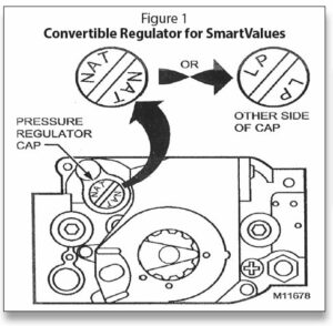
Convertible (Natural/LP) Regulator for Mobile Home Applications
Ignition system controls with the suffix letter R are convertible pressure regulator models. They can be converted from natural gas to liquid propane (LP), or from LP to natural gas, without a conversion kit.
Before converting the ignition control from one gas to another, check the ignition control label and the appliance manufacturer rating plate to determine if the factory-set pressure regulator setting meets the appliance manifold requirements after conversion.
Note: Convertible pressure regulator models (suffix letter R) do not have field-adjustable regulators.
If the factory pressure regulator setting meets the appliance manifold requirement, convert the ignition control using the following procedure:
1. Remove the pressure regulator cap (see Figure 1).
2. Turn over the cap so the letters facing up are for the gas type the appliance uses—NAT for natural gas and LP for liquid propane gas.
3. Replace the cap and tighten firmly.
The original SmartValve had continuous trial for pilot ignition; the igniter and pilot gas would remain on indefinitely as illustrated in Figure 2.

SmartValve Generation II is a continuous retry version. It attempts to ignite with the igniter on and pilot gas flowing for 90 seconds. If there is not any ignition, then the igniter and pilot gas will shut down for five minutes. This is shown in Figure 3. The system will continue this sequence until ignition takes place or the power is shut off. There is not enough gas escaping during the try for ignition to reach the lower explosive limit of either natural or LP gases.
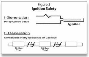
There is safety designed into the circuits, as the igniter is part of the valve control circuit. If the igniter is broken or otherwise electrically open, the valves cannot be opened; it is fail- safe.
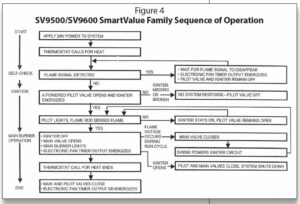
Figure 4 is the sequence of operation for the older Generation I system. Depending on the version, there may be a different sequence of operation with Generation II as shown in Figure 5.
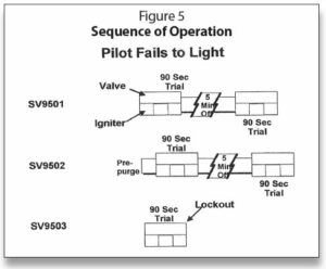
The SV9501 is the regular 90-second trial with the five-minute shutdown. The SV9502 will have the same trial times but will add prepurge at the beginning.
The SV9503 version is a single try with immediate hard lockout if ignition does not take place on the first try. This will require shutting the power off and reattempting another try for ignition. This system is used on many decorative fireplaces that use a switch on the wall to start the fireplace.
The sequence of operation illustrated in Figure 6 on a call for heat is that the pilot valve and igniter come on together when the thermostat calls for heat. The main burner opens only when the pilot is proved and remains open throughout the call for heat. The pilot burner also stays on during the entire call for heat. When the thermostat is satisfied, the pilot and main burner gas is shut off.
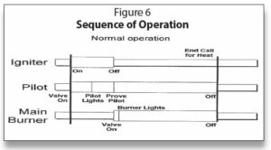
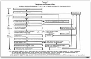
Figure 7 is the sequence of operation for the Generation II SmartValves.
In the next series, we will explore SmartValve’s typical wiring. ICM
Timmie M. McElwain is President of Gas Appliance Service, which provides training for those servicing gas combustion equipment. He is a certified instructor and test proctor for the Propane Gas Association in their CETP program.
As we look into some more modern systems and what specific problems they present, it is important to understand the basic fundamentals associated with these systems.
Most of our modern heating equipment in some way or another involves electronics, and with the electronics, the use of Flame Rectification as a safety and flame-proving system.
It does not matter if it is a forced warm air furnace or a forced hot water boiler—the same basic system is used to perform safe ignition and then consistent operation throughout the entire call for heat.
There are however different ways it is applied from Intermittent Pilot Application to Direct Spark Ignition and including Hot Surface Ignition. Each has its own distinct advantages and problems.
I invite you to visit our new Facebook page, Timmie’s Tips on Gas, located at facebook.com/groups/timmiesgastips. I look forward to seeing you there.
Universal Gas Valves Systems
In this section we are going to discuss Universal Gas Valves systems—in particular the Robertshaw 720-079 Gas Valve Uni-Kit. We will present some of the basics initially, then the installation and finally get into troubleshooting.
The 720-079 is designed to work equally well on Intermittent Pilot, Direct Spark and Hot Surface Ignition. Its features include:
• Dual automatic valves (redundant)
• Wiring connections, manual selector and adjustments on top of the valve
• Meets all codes requiring dual valve safety shutoff
• Reduces service truck stock-freeing up valuable space and saving money.

The 720-079 shown in Figure 1 features a manual selector, wiring connections and adjustments that are all easily accessible on the top of the valve. The 720-079 Uni-Kit has 1/2″ side outlets and a pressure regulator that is preset at 3.5″ water column (WC) for natural gas. For liquefied petroleum (LP) gas applications, the valve can be converted by using a pressure regulator conversion kit that is included.
The 720-079 incorporates a manual valve, pilot valve (dual automatic valves) and a main gas pressure regulator all in a small compact valve with a swing radius of 3–9/16″. The small size of the 720-079 lends itself to replacing many original equipment manufacturer (OEM) and competitive valves. The 720-079 is multiposition and can be mounted in any position, except upside-down.

The red manual selector arm easily identifies the 720-079 shown in Figure 2. In fact, all Robertshaw 7200 series valves with this arm are dual seated valves. The valve also features side outlets, which can be plugged if not used. Also illustrated are the inlet and outlet pressure taps and the regulator adjustment cap.

Figure 3 illustrates the capacities for different inlet and outlet sizes for the 7200 series. The 720-079 as shown in the ordering data is ½” x ¾” valve with a capacity of 150,000 BTUs. The cross-references in Table 1 cover White-Rodgers and Honeywell Valves.

Intermittent Pilot: Pilot Tubing
Figure 4 illustrates the installation instructions and wiring for intermittent pilot applications. The instructions for pilot tubing are as follows:
1. Make sure tubing is free of burns and dirt.
2. The pilot orifice must be checked and cleaned if necessary at this time.
3. Connect pilot tubing into the control using fitting provided and tighten for a gas tight seal.
Wiring
DO NOT short gas valve terminals. This will damage the wall thermostat and void the warranty.
1. Check the system for the proper transformer by comparing the volt amps (VA) ratings of the transformer and the system. The system rating is determined by multiplying the voltage draw x the amp draw. Normally 20VA transformers are sufficient for heating only applications and 40VA for heating/cooling applications. (Note: improper transformer VA rating will cause erratic system operation).
2. Connect the wire from the “MV” terminal on the ignition control unit to the “M” terminal on the gas valve.
3. Connect the wire from the “PV” terminal on the ignition control unit to the “P” terminal on the gas valve.
4. Connect the wire from the “MV/PV” terminal on the ignition control unit to the “C” terminal on the gas valve.
 Hot Surface Applications: Pilot Tubing
Figure 5 shows the wiring and instructions for hot surface ignition (HSI) applications. The pilot plug must be in place as there is no need for a pilot. It can be either local sense using the igniter as a sensor or remote sense with a separate flame sensor. The instructions for pilot tubing are as follows:
Note: Some hot surface applications use the pilot outlet. If so, proceed as directed below. If not used, install pilot outlet tubing plug packaged in the 720-079 gas valve kit, then proceed to “wiring.”
1. Make sure tubing is free of burns and dirt.
2. We strongly recommend that the pilot orifice be checked and cleaned if necessary at this time.
3. Connect pilot tubing into the control using fitting provided, and tighten for a gas-tight seal.
Wiring
DO NOT short gas valve terminals. This will damage the wall thermostat and void the warranty.
1. Check the system for the proper transformer by comparing the VA ratings of the transformer and the system. The system rating is determined by multiplying the voltage draw x the amp draw. Normally 20VA transformers are sufficient for heating only applications and 40VA for heating /cooling applications. (Note: improper transformer VA ratings will cause erratic system operation).
2. Locate the white wire terminal adaptor (jumper) that is included with the 720-079 gas valve.
3. Connect the white wire terminal adaptor to the “M” and “P” terminals on the 720-079 gas valve.
4. Determine which wire was connected to the “main valve” terminal on the original valve. Connect this wire to the remaining terminal on the white wire terminal adaptor.

Direct Spark: Pilot Outlet
Figure 6 illustrates the wiring and instructions for direct spark ignition either remote or direct sense. The installation instructions for the pilot outlet are:
First, install the pilot tubing plug packaged in the 720-079 gas valve.
Wiring
DO NOT short gas valve terminals. This will damage the wall thermostat and void the warranty.
1. Check the system for the proper transformer by comparing the VA ratings of the transformer and the system. The system rating is determined by multiplying the voltage draw x the amp draw. Normally, 20VA transformers are sufficient for heating-only applications and 40VA for heating/cooling applications. (Note: improper transformer VA rating will cause erratic system operation).
2. Locate the white wire terminal adaptor (jumper) that is included with the 720-079 gas valve.
3. Connect the white wire terminal adaptor to the “M” and “P” terminals on the 720-079 gas valve.
4. Determine which wire was connected to the “main valve” terminal on the original valve. Connect this wire to the remaining terminal on the white wire terminal adaptor.
5. Connect the remaining wire from the original gas valve to the “C” terminal on the 720-079 gas valve.

Operating Instructions
The operating instructions are as follows:
1. Turn the wall thermostat to its lowest setting. Remove burner access panel(s). Selector arm must only be operated by hand (see illustration in Figure 7). Do not use pliers, wrenches or other tools to operate the arm. The selector arm cannot be moved into the Off position without first depressing the lever in the On position.
2. Move selector arm to the Off position.
3. WARNING: Wait at least five minutes to allow any gas in the combustion chamber to vent; if you then smell gas in the appliance area or near the floor, STOP and follow warning instructions. Failure to do so may result in fire or explosion.
4. Move selector arm to the On position, and set room thermostat to desired temperature. Allow burner to cycle on and off.
5. Leak test with a soap solution after installing with main burner on. Coat pipe and tubing joints, gasket, etc. with soap solution. Bubbles indicate leaks.
6. Replace burner access panel.
Pressure Regulator Adjustments
An adjustment of the pressure regulator is not normally necessary since it is preset at the factory. It may need to be adjusted, however, to maximize the combustion efficiency of the equipment. (Note: manometer attachment may be accomplished at pressure tap plug, above control outlet, as shown in Figure 7. It is also a good idea to measure inlet pressure at the tap on the other side of the valve). Field adjustment may be accomplished as follows:
1. Manometer or gauge attachments may be accomplished at pressure tap plug (D).
2. Remove regulator adjustment screw cap (top of control-A).
3. With small screwdriver, rotate adjustment screw (B) clockwise to increase, or counterclockwise to decrease, pressure to comply with manufacturer’s specifications.
4. Replace regulator adjustment screw cap (A).

Regulator Conversion
Caution: main burner and pilot orifices must be changed when regulator is converted from one type of gas to another.
1. Turn off gas and electricity to appliance.
2. Remove slotted cap (A), adjusting screw (B) and natural gas spring—not color-coded— (C), from control.
3. Install new LP spring—color-coded with a black strip.
4. Install new adjusting screw (B).
5. Attach manometer or pressure gauge at the outlet pressure tap (D).
6. Turn gas and electricity on.
7. Turn room thermostat to call for heat.
8. With burner on, adjust screw (B) to supply LP gas to pressure as recommended by the appliance manufacturer.
9. If adjusting screw (B) reaches its maximum depth (bottoms out) before recommended pressure setting is reached, turn screw counterclockwise until pressure drops slightly (approximately 0.1″ WC)
WARNING: do not stretch or alter spring.
10. Turn off gas and electricity to appliance.
11. Remove manometer or pressure gauge and reinstall pressure tap outlet plug (D).
12. Install new red slotted cap in place of (A).
13. Turn gas and electricity On.
14. With burner operating, immediately check all fittings for leaks with soap solution. Bubbles indicate leaks that must be corrected.
15. Conduct a combustion test on the equipment to determine safe and efficient firing of the equipment.
16. Attach label to show control has been converted to LP.
17. Set room thermostat to desired temperature.
In this article, we will discuss Universal Gas Valves systems, in particular the White Rodgers 36E98-304 Universal Slow Opening Gas Valve. We will present some of the basics initially, then the installation and finally get into troubleshooting.
The 36E98-304-combination gas valve illustrated in Figure 1 is designed for intermittent ignition, direct spark ignition and hot surface ignition system applications. The valve is equipped with a redundant solenoid valve that controls gas flow to the pilot and main burners, a main valve that controls gas flow to the main burner, a pressure regulator to maintain a constant outlet pressure and a two-position gas cock knob for manual gas shut off. It uses a 0.008 internal orifice to cause the slow opening affect. Do not use this valve to replace White-Rodgers 36E02, 36E37 or 36E97 slow opening valves; they use different orifices and have different opening characteristics.

The pipe size/capacities are from 3/8″x 3/8″ giving 75,000 British Thermal Units (BTUs) for natural gas and 121,500 for liquefied petroleum (LP) gas to 0.5″x 0.75″ giving 125,000 for natural gas and 202,800 for LP gas.

The valves are shipped with the pilot outlet plugged. For installations requiring a pilot, remove the plug and use the fitting supplied separately with the control. Figure 2 shows location of pilot outlet along with outlet pressure tap. Features include:
1. Poppet style manual valve (capable of withstanding high inlet pressures)
2. Conical inlet and outlet screens protected from pipe damage
3. High sealing force direct acting solenoid valves
4. Controlled gasket clinch between castings to with stand high inlet pressures
5. Tamper-resistant screws
6. Automated assembly and test
Figure 3 shows the correct piping procedures. Figure 4 illustrates the internal operation of the gas valve.


Valve features and performance
The next few sections illustrate some of the features and options on this valve series. Not all of these features may be found on equipment you run into but they are options that Original Equipment Manufacturers (OEMs) can choose for their particular equipment.
Table 1 illustrates the particulars of the one-inch pressure drop capacity.

Features & Options: Fast Open Control
This control has a fast-opening characteristic that is suitable for a wide range of applications. It provides a fast rise to full pressure upon energizing the main and redundant solenoid. Regulator spring conversion kits are available for this control.
Features & Options:
Slow Open Control
This control has slow opening characteristic. It provides a slow increase of gas to full pressure for smoother ignition, as may be required by some applications. There is also a 36E36-304 fast opening valve from White-Rodgers that is classified a universal replacement valve. There is a cross-reference for this valve in Table 2. It has all the other wiring and other characteristics of the 36E98-304 other than its opening time.
Intermittent Pilot Directions


See Figure 5.
1. Connect wire from “MV” terminal on ignition control unit to “M” terminal on gas valve.
2. Connect wire from “PV” terminal on ignition control unit to “P” terminal on gas valve.
3. Connect wire from “MV/PV” terminal on ignition control unit to “C” terminal on gas valve.

Hot Surface Ignition Directions
See Figure 6.
1. Connect tan wire terminal adaptor (jumper) included with gas valve to “M” and “P” terminals on gas valve.
2. Determine which wire was connected to “Main Valve” terminal on original valve. Connect this wire to remaining terminal of the tan terminal adaptor.
Features & Options: Delay Open Control
This control has delayed opening characteristic. This control is equipped with a pressure switch system.
Features & Options: Step Open Control
This control has a step open feature that regluates the outlet to an initial step pressure (non-field adjustable) and rises to the full outlet pressure. It provides a step pressure for softer ignition.
Features & Options: Two-Stage Control
This control has a two-stage feature. Upon energizing the main and redundant control valves, the servo regulator will provide a low fire rate until the high fire solenoid is energized. (Field adjustable on both low fire and high fire).
Features & Options: Convertible Control
The convertible regulator option for this control involves a construction that permits easy Natural to LP conversion (or vice versa) by removing, inverting and replacing the regluator cap screw. This feature easily lends inself to use in mobile homes and infra-red applications.
Table 2 gives the cross-reference for the 36E98-304-gas valve and includes the OEMs that use the old part listed.
Adjustment
Hot Surface or Direct Burner Ignition Systems Install jumper wire across M-1 and P-3 terminals. This will open both redundant valves together.
Manual Valve Knob
The manual valve knob is a two-position (on-off) type. To turn manual valve On, rotate knob clockwise or counterclockwise to line up the word On on the knob with the indicator on the cover casting as shown in Figure 7. To turn manual valve Off, rotate knob clockwise or counter-clockwise to line up the word Off on the knob with the indicator on the cover casting.

Pilot Gas Adjustment
These controls are factory preset to provide proper pilot gas flow for most applications. If additional adjustment is necessary, follow these steps:
1. Turn off all electrical power to the system before making any adjustments.
2. Remove the pilot adjust cover screw and gasket to expose the adjusting screw shown in Figure 8. Turn the adjusting screw clockwise to reduce pilot flame, or counterclockwise to increase pilot flame.
3. Replace the gasket and pilot adjust cover screw and tighten securely.
4. Restore power to the system.

Pressure Regulator Adjustment
These controls are shipped from the factory with the regulator set for 3.5″ W.C. (natural gas, full flow). Consult the appliance rating plate to ensure burner manifold pressure; it should be 3.5″ W.C. If another outlet pressure is required, follow these steps. If a valve has been factory-adjusted for the 2.5″–5″ W.C. range, it cannot be field-adjusted outside that range. This is also true for valves adjusted to the 7.5″–12″ W.C. range for LP gas.
1. Turn off all electrical power to the system.
2. Attach a manometer to the outlet pressure tap of the valve.
3. Turn on system power and energize valve.
4. Remove regulator cover screw and turn regulator adjust screw clockwise to increase pressure, or counterclockwise to decrease pressure, as shown in Figure 8. Always adjust regulator to provide the correct pressure according to the OEM’s specifications listed on the appliance rating plate.
5. Replace regulator cover screw and tighten securely.
Figure 9 is a top view of the valve showing the manual knob, pilot solenoid, electrical panel, main solenoid and the adjustment for the regulator. On all gas valves, only main gas is regulated. The pilot is on line pressure and is adjusted by the screw, to the right of the manual knob.

Please contact assteditor@indoorcomfortmarketing.com for graphs concerning the 1″ pressure drop capacity and performance curves for the gas valves in this series, as well as an overview of gas valve models available. ICM
————————————————————-
Timmie M. McElwain is President of Gas Appliance Service, which provides training for those servicing gas combustion equipment. He is a certified instructor and test proctor for the Propane Gas Association in their CETP program.
Part One appeared in the September/October 2020 Indoor Comfort.
Operation
The VR8345 gas controls, Figure 9, provide an “On-Off” manual control of gas flow. In he Off position, pilot and/or main burner gas flow is prevented. In the On position, pilot and/or main burner gas flow is under control of the thermostat, the Direct Spark Ignition System (DSI) module, Hot Surface Ignition System (HSI) module/intermittent pilot module and the gas valve.

Direct Spark Ignition/Hot Surface Ignition Applications
System operation
When the thermostat calls for heat, the DSI or HSI module is energized, Figures 10 & 11. The module activates the first and second automatic valves of the gas control, which allows main burner gas flow. At the same time, the DSI/HSI module generates a spark at the igniter-sensor to light the main burner. The second automatic valve diaphragm, controlled by the servo pressure regulator, opens and adjusts gas flow as long as the system is powered. The servo pressure regulator monitors outlet pressure to provide an even main burner gas flow. Loss of power (thermostat satisfied) de-energizes the DSI/HSI module and closes the automatic valves. The system is ready to return to normal service when power is restored through the thermostat.
If the igniter-sensor stops detecting a flame at the main burner (lack of adequate microamp signal back to the module), then the trial for ignition is restarted. On DSI/HSI modules with lock-out timers, the automatic valves are de-energized and ignition stops after the lock-out period. On modules without lock-out timers, the trial for ignition continues indefinitely and the first automatic valves remain open.
If the main burner flame is restarted successfully, operation continues as described above. Gas control operation is described in more detail below.


Valve position during thermostat “Off” cycle
The valve is positioned as shown in Figure 12 when the:
• Gas control knob is in the On position.
• Thermostat is not calling for heat.
The first automatic valve is closed. The second automatic valve operator is de-energized, closing the channel to the pressure regulator, and opening a channel to the underside of the second automatic valve diaphragm. The combination of spring pressure under the second automatic valve diaphragm and lack of outlet pressure hold the diaphragm firmly closed. Both valves block the main burner gas flow.

When the thermostat calls for heat
When the thermostat calls for heat, the DI module generates a spark at the main burner and the first automatic valve and second automatic valve operators are energized (Figure 13). The first automatic valve opens, and the second automatic valve operator valve disk is lifted off its seat. This diverts gas flow from the second automatic valve diaphragm and causes a reduction of pressure on the underside of this diaphragm. The reduced pressure on the bottom of the automatic valve diaphragm repositions the diaphragm downward, away from the valve seat, allowing main burner gas flow.

Intermittent Pilot Applications
System operation
When the thermostat calls for heat, the S8600 Intermittent Pilot Module is energized. The S8600, in turn, activates the first automatic valve of the gas control, allowing pilot gas flow. Simultaneously, the S8600 module generates a spark at the igniter-sensor and lights the pilot. The pilot flame is then sensed by the igniter-sensor, and spark generation ends.
After the pilot is lit, the S8600 module energizes the solenoid for the second automatic valve operator (the first automatic valve remains energized). This is dependent upon an adequate microamp signal being produced as the flame is sensed by the igniter-sensor. That signal should be in the range of 2–10 microamps (3–5 being the normal range).
The second automatic valve diaphragm, controlled by a servo pressure regulator, opens and adjusts main gas flow as long as the system is powered and the pilot is burning. The servo pressure regulator monitors outlet pressure to provide an even main burner gas flow.
Loss of power (thermostat satisfied) de-energizes the S8600 module and closes both automatic valves. The system is then ready for the next cycle.
Loss of pilot flame, or when the flame is too small to reliably light the main burner, closes the second automatic valve operator. The S8600 module then attempts to restart the pilot. On S8600 modules with lock-out timers, the first automatic valve closes after the lockout period. On S8600 modules without lock-out timers, the trial for ignition continues indefinitely and the first automatic valve remains open.
If the pilot flame is restarted successfully, the main burner is reopened, and gas flows to the main burner as described above. Gas control operation is described in more detail below.
Valve position during thermostat “Off” cycle
The valve is positioned as shown in Figure 14 when the:
• Manual gas control now is in the On position.
• Thermostat is not calling for heat.
The first automatic valve is closed. The second automatic valve operator is de-energized, closing the channel to the pressure regulator, and opening a channel to the under-side of the second automatic valve diaphragm. The combination of the spring pressure under the second automatic valve diaphragm and lack of outlet pressure hold the diaphragm firmly closed (gas pilot burner gas flow is prevented by the first automatic valve and the main burner by both valves).

When Thermostat Calls for Heat
When the thermostat calls for heat, the trial for pilot ignition begins. The first automatic valve solenoid is energized by the module and opens, allowing pilot burner gas flow. Gas also flows to the second automatic valve operator, but is mechanically blocked at the operator (see Figure 12).
After the pilot lights and the pilot flame is sensed by the igniter-sensor, the second automatic valve solenoid is energized by the module, and the second automatic operator valve is lifted off its seat (see Figure 13). This diverts gas flow from the second automatic valve diaphragm and causes a reduction of pressure on the underside of this diaphragm. The reduced pressure on the bottom of the automatic valve diaphragm repositions the diaphragm downward, away from the valve seat, allowing main burner gas flow.
All Applications
During the On cycle, the servo pressure regulator provides close control of outlet pressure; even if inlet pressure and flow rate vary widely. Any outlet pressure change is immediately reflected back to the pressure regulator diaphragm, which repositions to change the flow rate through the regulator and, thus, through the automatic valve.
If outlet pressure begins to rise, the pressure regulator diaphragm moves slightly higher, allowing less gas flow to the gas control outlet. This increases gas pressure under the automatic valve diaphragm and repositions the valve disk closer to the seat. Thus, flow of gas through the second automatic valve is reduced and outlet pressure falls to the desired level.
If outlet pressure begins to fall, the pressure regulator diaphragm moves slightly lower, allowing more gas flow to the gas control outlet. This decreases gas pressure under the second automatic valve diaphragm and repositions the valve disk further from the seat. Thus, flow of gas through the second automatic valve is increased, and outlet pressure rises to the desired level.
When the call for heat ends
When the call for heat ends, the first automatic valve and the second automatic valve operator close, bypassing the regulator(s) and shutting off the main burner (and in the intermittent pilot application, the pilot gas flow). As pressure inside the gas control and underneath the automatic valve diaphragm equalizes, spring pressure closes the second automatic valve to provide a second barrier to gas flow. ICM
The importance of universal controls cannot be emphasized enough. The ability to carry one control that covers a multitude of applications makes the service technician’s job a lot easier. There are other control systems that also have universal controls that can be used. We are seeing electronic fan timers with a universal board that replaces many controls. We will be discussing some of those in later articles. There are also universal integrated furnace controls. Keeping truck stock simple and convenient is what it is all about.
Honeywell’s VR8345M Universal Electronic Ignition Gas Control (Figure 1) is used in gasfired equipment with capacities up to 300 cubic feet per hour at a one-inch water column pressure drop for natural gas. The VR8345M will operate with direct spark ignition (DSI), hot surface ignition (HSI) or intermittent pilot ignition.

The control includes a manual valve, two automatic operators, a pressure regulator, pilot adjustment, pilot plug and ignition adapter. It is also:
• Compatible with hot surface pilot, intermittent pilot and direct spark ignition.
• Replaces virtually any IP, HSI or DSI gas control.
• For use with 24 VAC heating appliances that burn natural or manufactured gas or liquefied petroleum (LP) gas (it includes a converter kit to adapt from natural gas to LP gas).
• Compact to fit into tightly packed, high efficiency heating equipment.
• Works with virtually all residential equipment and all but the largest commercial equipment, with a regulation capacity range of 30,000 to 415,000 BTU per hour natural gas (48,600 to 672,300 LP gas).
• All adjustments and wiring connections are accessible from the top of the control.
• Has a straight-through body pattern.
• Includes 1/8-inch NPT inlet and outlet taps on top of the gas control to aid the adjustment of gas pressure in problem installations.
• The 3/4-inch x 3/4-inch inlet and outlet fit easily on high capacity systems, as well as others, using 1/2-inch reducer bushings.
• A 4-inch swing radius allows easy rotation into position inside the tightest furnace vestibules.
• It can be installed at any angle, including vertically between 0–90° from the upright position.
• Its clearly marked, keyed terminal block allows quick attachment of wires and IP/DSI/HSI jumper. A keyed jumper cannot be incorrectly inserted.
• The internal inlet screen blocks contaminants in the gas line from entering the valve.

• Has a -40°F to + 175°F (-40°C to +79°C) temperature range standard.
• Features a standard opening.

There is a cross-reference available online that gives the cross-reference for Honeywell valves, which replace White-Rodgers, Robertshaw and Honeywell valves. The VR8345M- 4302 replaces all of them. Be sure to make note of the footnotes that follow the cross-reference.
In Figure 2, the procedure for applying pipe dope isshown along with the table “NPT Pipe Thread Length in Inches” which is the requirement for NPT (National Pipe Thread) thread length in inches for different size pipe. Teflon tape should not be used at the gas valve as pieces of the tape may break off and end up inside the gas valve.
It should be noted that for Figure 2, the table NPT Pipe Thread Length in Inches applies to all connections of piping to gas valves.

Figure 3 illustrates the requirement for a sediment trap with all gas valve installations. The valve comes with a plug in the pilot tubing outlet for use with DSI and HSI. When using the valve on intermittent pilot, the plug must be removed.

Figure 4 gives a top view of the control for ease of locating inlet and outlet pressure tap, pilot adjustment and pressure regulator adjustment.

Figure 5 shows the proper use of wrenches when installing the valve. These procedures apply to all gas valve installations, not just Honeywell.

Figure 6 shows the installation of pilot tubing into the valve. It is important to always replace the nut and ferrule and use new ones.

Figure 7 shows the installation of the pilot tubing into the valve for intermittent pilot applications.
 Figure 8 shows the adapter installation required when using the valve for HSI or DSI applications. The adapter only plugs in one way so you can’t make a mistake. The pilot gas plug must be in place when using the valve on direct burner applications.
This ends Part 1. The next issue will pick-up with universal gas valves operation in various applications. ICM
Part 1 (from May/Jun Indoor Comfort)
This discussion will give some direct application of procedures for troubleshooting hot surface ignition controls. It will not address their use with integrated boiler or furnace controls.
Figure 1 is an example of a very simple application of hot surface ignition using silicon carbide igniters. We will address silicon nitride igniters later in this discussion.

The two igniters from Norton in Table 1 point out the various characteristics of the different igniters they produce. The emphasis here will be on the heating application only using the Norton 201 and 271 igniters, which are 120-volt igniters that have been used extensively for a number of years. Norton introduced mini-igniters in 1988 and my first contact with them was in 1993.

The Norton 401, 24-volt igniter is used with Honeywell Smart Valve Generation I, II and III (SV9540 and SV9640). With the advent of Honeywell Generation III, we see the Norton 601 igniter, which is a 120-volt igniter, used with Smart Valve SV9510/9520 and SV9610/9620.
The Norton 401, 24 volts has a very short warmup time (three seconds) due to it being a silicon-nitride material. It has a low resistance to cold (1–4 ohms) and therefore heats up much more quickly than standard 120-volt silicon-carbide igniters. The Norton 601, 120-
volt igniter also has a short warm-up time (five seconds) with a cold resistance of 50–300 ohms. It should be mentioned here that Norton (Coorstek) also makes Gas Dryer Igniters (the 101) and Gas Range Igniters (the 501).
The igniters shown in Figure 2 are all model 271 17-second warmup time igniters from Norton. The exception is the igniter on the lower right-hand side—the 41-413—which is the igniter used by Carlin for its G3A and G3B power gas conversion burners. It is a 34-second igniter. As you observe the different igniters, the main difference is not the igniter portion itself; they are all basically the same. What is different is the ceramic connector and wiring harness. The wiring harnesses can be cut and wire nuts used if necessary to do so.

Hot Surface Operation
The silicon carbide element can be handled without damage; however, it is better and safer to handle the igniter by the ceramic holder. The myth that the silicon carbide tip cannot be handled because body oils cause contamination is untrue.
On a typical heating system with hot surface ignition, a call for heat (thermostat contacts closed) will send a 24-volt signal to the igniter module. When energized, the module will power-up the igniter. If the module is a pre-purge model, it will delay 15 or 30 seconds before the igniter is activated. On pre-purge models, the module will energize the combustion blower or other relays at the beginning of the cycle.
Once the pre-purge timing is up (if so equipped), the silicon carbide igniter heats up to proper ignition temperature (above 1,800°F) in either 17 or 34 seconds, 20 or 40 seconds for some models, depending on the manufacturer of the module. NOTE: A 17- or 20-second igniter can be used on a 34- or 40-second application, but you could not use a 17- or 20-second module with a 34- or 40-second igniter.
It should be noted here that the igniters are made by Norton (now Coorstek), Carborundum (now Surface Igniter Corp.), Igniter Systems Inc. and some other small companies. For purposes of replacement, the Norton Igniters are distributed by Robertshaw. See 41-400 series for replacement. White Rodgers has its own line of igniters (the 767A series).
At the end of the igniter warm-up period, the gas valve main valve opens. The igniter will remain on for a specific amount of time (seconds) depending on the specific ignition module being used. This “ON” time, or trial for ignition time, can vary depending on the specific ignition module being used. When main burner ignition occurs, the flame is sensed by the igniter (local sense) or by a remote sensor (remote sense). With main burner flame established, the igniter is turned off (120 volts is shut-off to igniter).
NOTE: The burner flame must be detected within the timed trial for ignition. If no flame is detected, the gas main valve is de-energized, shutting off the gas flow. The system may go into lockout, or if it has retry model, it will retry the number of times allocated.

Hot Surface Ignition issues
In some respects, Hot Surface Ignition (HSI) troubleshooting is somewhat more complicated; Figure 3 illustrates this.
• It is not always clear whether you are looking at a pre-purge period or an igniter warm-up period.
• Some of the sequences of operation used with HSI are really complex; if you don’t know what to look for, you may falsely conclude that it is faulty.
• Ignition trials are very short (a few seconds), so sometimes you may have to make measurements fast.
Some preliminary checks can be made on HSI systems that will many times find the problem. The four basic questions that follow can many times pinpoint the problem (see Figures 4-8).


Hot Surface Ignition Troubleshooting
The troubleshooting procedures that follow are more detailed and cover each problem, possible cause, solutions and procedures.
PROBLEM #1: Hot Surface Igniter Does Not Glow Remember to wait for pre-purge time (on models so equipped). Possible causes:
• No main power
• Faulty transformer
• Faulty thermostat
• Faulty limit switch
• Faulty blower interlock switch (pressure switch, combustion blower proving switch)
• Faulty hot surface igniter
• Faulty ignition control or integrated control
SOLUTION #1:
Perform normal system checks of main power, secondary of transformer, etc. With power on and thermostat calling, check voltage at 24V or TH to 24V ground at the module or integrated control. If no 24 volts, check the transformer. Also check other controls in the circuit from transformer to module or integrated control. Check for 120 volts from (L1) to Neutral (L2), check for 120 volts from “IGN” TO “IGN” or on some modules from the HSI terminals. If you have 24 volts to module or integrated control and 120 volts and no 120 or 24 volts out of the module or integrated control, the module or control is faulty. Check the amperage draw of igniter with AMP meter or AMPROBE amperage; it should not exceed 4.75 amps.

PROCEDURE:
1. Perform a visual check of the igniter for signs of damage or cracks. The sleeving over the wire should be examined for chafing, burned portions or cuts in the wire. The connectors should be properly seated and free from oxidation and/or corrosion. Look for “hot spots” on the igniter, as in Figure 9. Also pull on the wires to make sure they have not become disconnected inside the ceramic holder. Observe the igniter during heat up. If a bright, white line across one of the igniter legs is detected, a crack may exist that could cause premature failure. Allow the igniter to cool and perform a resistance test. Additional signs of a crack are an “open” igniter (that shows no continuity when tested) or a buildup of white silica dust around the bright spot. Replace the igniter if you see these cracks.
2. There are several possible causes for repeated igniter failures—one would be high supply voltage. Hot surface igniters can burn out at approximately 132 volts. Even voltages in excess of 125 volts may reduce igniter life. If high voltage is present, request the power company lowers the power.
3. Other causes for igniter failure include drywall dust, fiberglass insulation, sealants or other contaminants that may accumulate on the igniter. In some cases condensate dripping on the igniter causes it to fail. Some sort of protection above the igniter will prevent this from happening again.
4. Furnace or boiler short-cycling, delayed ignition or an over-gassed condition are also contributors to shortened igniter life.
Perform a resistance test on the igniter
PROCEDURE:
The manufacturer recommends performing a simple room temperature resistance (RTR) test after installing the igniter (remember to disconnect the leads to ensure that only the resistance of the igniter is measured). If the RTR is not to specification as shown in Table 1 for igniter Model 201, which is a 34-second warmup time igniter of 45–400 ohms, or the igniter Model 271, which is a 17-second warmup time igniter of 40–75 ohms, then the silicone tip is damaged in some way and should be replaced. When troubleshooting an appliance where the igniter is suspect, the RTR will be higher on a used igniter; the resistance should be no more than double the original resistance at installation. The 201 is 90–800 ohms; the 271 is 80–150 ohms.
PROBLEM #2: Igniter Glows but Main Burner Will Not Light
Possible causes:
• Improper igniter alignment
• Faulty ignition control
• Faulty gas valve
• High inlet pressure (LP gas)
• Polarity reversed
• No earth ground
SOLUTION #2
Make sure gas is available at gas valve. Too high pressure will lock-up the gas valve. Check and make sure polarity is correct. Make sure the igniter is in position (you cannot move the igniter from its designed position). Check for a good earth ground from L1 to the furnace chassis—you should read 120 volts; if not, check and or repair ignition ground wire or ignition control mounting screws. A jumper from ground to gas line should give a good ground. Check for 24 volts to gas valve; if yes and valve does not open, replace valve; if no, replace ignition module.
PROCEDURE:
1. If the igniter is going to be used as a sensor, then make sure the flame is capable of providing a good rectification signal. Make sure that about 3/4″ to 1″ of the flame sensor or igniter sensor is continuously immersed in the flame for the best flame signal. Bend the bracket or the flame sensor and/or relocate the sensor as necessary. Do not relocate an igniter or combination igniter-sensor.
2. Check for excessive (over 1,000°F or 538°C) temperature at the ceramic insulator on the flame sensor. Excessive temperature can cause a short to ground; move the sensor to a cooler location or shield the insulator. Do not relocate an igniter or combination ignitersensor.
3. Check for cracked ceramic insulator, which can cause a short to ground, and replace the sensor if necessary.
a. Make sure that the electrical connections are clean and tight. Replace damaged wire with moisture-resistant No. 18 wire rated for continuous duty up to 105°C (221°F).
PROBLEM# 3: Main Burner Shuts Off Before the Thermostat is Satisfied
Possible causes:
• Improper igniter alignment
• Faulty ignition control
• Contaminated igniter and/or sensor (remote senses)
• Bad burner ground
SOLUTION #3
Check for proper polarity. Check for proper igniter position; make sure proper ignition control is grounded. Check for foreign matter on igniter or sensor. Clean or replace. Check main burner ground by checking continuity between ground and burner. If previous checks are okay, you may need to check the microamps on the system.
Part 2 (from Jul/Aug Indoor Comfort)
When checking the flame signal, it is important to realize that when a hot surface igniter (HSI) is also being used as a sensor, there will be some difficulty in checking the micro-amps. There are several procedures you can follow. In my opinion, the procedure in Figure 1 is the preferred method. It is also important to note the technical bulletin from Norton (Coorstek) points out that the igniter can have a buildup of oxide that can cause it to be a poor sensor.
It has been my observation that when the igniter is used on atmospheric burners, exposing the igniter to whatever contaminants are in the room, the igniter is a poor sensor. Atmospheric burners tend to work a little better when the igniter is used in a sealed combustion chamber that gets its air for combustion from the outdoors.
Direct Sense: The Igniter as a Flame Rod
Sensing through flame rectification, whether “direct” (through the igniter) or “remote” (separate flame rod), involves certain components and variables. The object is to use the ionized particles in the flame (burning gas) to conduct a current and complete an electrical circuit.
The control module initiates an AC signal that is sent out to the igniter. The flame acts as a diode and converts the AC signal to a rectified DC signal. The strength of the signal required to prove flame, and therefore keep the gas valve open, is dependent on the control module and varies from one control manufacturer’s board to another.
Signal strength can be affected by:
• the type of burner,
• the position of the igniter in the flame,
• the age of the igniter,
• the type of gas,
• coating on the igniter and
• any impurities that build up on the system over time.
It is imperative that the flame remains in contact with the burner, and that the burner and control module have the same common ground.
When using the igniter as the sense unit, it is important to remember that as an igniter ages, a thin oxide (Si02) layer is formed on the surface. This is part of the normal aging process of a silicon carbide igniter. As this oxide layer is formed, it actually helps seal the underlying SiC grains and inhibits further rapid oxidation. The silica (silicon oxide) that has formed is a glass, which is an insulator and will diminish the strength of the flame signal that is being sent out. Whether the signal will still be strong enough to keep the valve open as the igniter ages is application-dependent.
Although direct sense can be a very feasible alternative, in the final analysis, it is the responsibility of the Original Equipment Manufacturer’s (OEM) testing to determine if it is a viable solution for the particular application.

Checking microamps with systems using the igniter as a sensor can sometimes be difficult. The problem is distinguishing between the 120 volts AC (VAC) power to get the igniter to glow and then reading the microamps created by the flame to igniter/sensor using the equipment burner as ground.
Figure 1 (previous page) was developed by the author of this article. It includes a list of parts needed to make the switch tester and the wiring to get the switch to work. Figure 3 shows microamp check with a separate sensor.
Hot Surface Igniters Replacements
The distributor for Norton (Coorstek) Igniters is Robertshaw Controls Co. They can be found in the latest Robertshaw Catalogs under the Uni-Line 41-400 catalog series for the Norton (Coorstek) 201 and 271 igniters. It should be pointed out that the igniters that are offered in the catalog are all 17-second warm-up time igniters (Norton 271) with one exception, which is the Norton 201 C (Robertshaw 41-413) used on the Carlin Gas Conversion burner only.
The Mini-igniters from Norton (Norton 601 series) are carried under the Robertshaw catalog series 41-600.
It should be noted that the basic difference between igniters is the ceramic base and the mounting brackets. This makes for some difficulty in using them interchangeably and this is not recommended. It is possible that the mated plug on the lead wires may not match up with the unit being replaced. In that case, the wires can be cut and wire nuts can be used to join the wires.


White Rodgers Control Co. also offers Silicon Carbide Igniters in its F767A series. It should be noted that items in the White Rodgers modules 50E47 series require a special wiring harness as shown in Figure 4.

When replacing White Rodgers with another module system, it requires a wiring change using the special adapter shown in Figure 4, which is included in all the universal module replacement kits, such as Honeywell S8910U.
One of the most helpful things to understand is that these igniters can be cross-referenced with one another in Figure 2 (see page 12). Figure 5 (see page 15) describes White-Rodgers’ silicon carbide HSIs in more depth.
There are several upgrade kits offered by the various manufacturers whose purpose is to convert from a Silicon Carbide Igniter over to a Silicon Nitride Igniter. White Rodgers offers the 21D64-2 Nitride Upgrade Kit. This kit does not need an extra module as the now obsolete 21D64-1 required. You can use the old module to change the igniter.
Honeywell supplies the Q3200U Universal Hot Surface Igniter Kit, designed to provide a robust field service replacement igniter in gas-fired appliances with Norton/St Gobain (Coorstek) 120 VAC silicon carbide HSIs. The Q3200U uses a 120-volt silicon nitride igniter design with long life and high resistance to damage or burnout in the appliance. The kit includes the specially-designed silicon nitride igniter and six different bracket configurations to adapt the igniter to the specific appliance application along with accessory parts to mount and wire the igniter. Clear instructions and application templates are provided to simplify selection of the proper bracket and ease installation of the replacement.
Robertshaw also offers the 41-400N Series, which is a collection of Silicon Nitride Igniters. They are produced by Kyocera and distributed through Robertshaw.
Also from Kyocera and distributed by Robertshaw are the 41-801N, 41-802N and the 41- 803. It is very important to note that these three igniters cannot be used as a flame sensor. A separate flame rod is required, such as Robertshaw 1751-729 (24″ lead) or 1751-749 (72″ lead).
This concludes the two-part presentation on Hot Surface Ignition Troubleshooting. We will cover Universal Electronic Ignition Gas Valves in the next article. ICM
Timmie M. McElwain is President of Gas Appliance Service, which provides training for those servicing gas combustion equipment. He is a certified instructor and test proctor for the Propane Gas Association in their CETP program.
There are only a few differences between gas and oil hydronics. An obvious one is that the burners and fuels involved are different. Controls on older equipment are, however, the same with some exceptions. In this series of articles I want to address the distinctions and how to work with them, along with diagnostics and how to solve problems between these two separate fuel systems. We will briefly address some steam related facts, but our focus will be on forced hot water systems used with gas—both natural and propane.
So far we have been emphasizing older systems in this series. In line with that theme, “New Technologies in Heating” will talk about a little about Modulating/Condensing equipment as gas systems. There are some controls unique to gas, and those are what we’ll want to address.
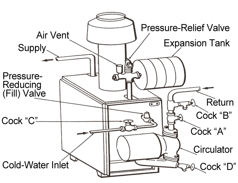
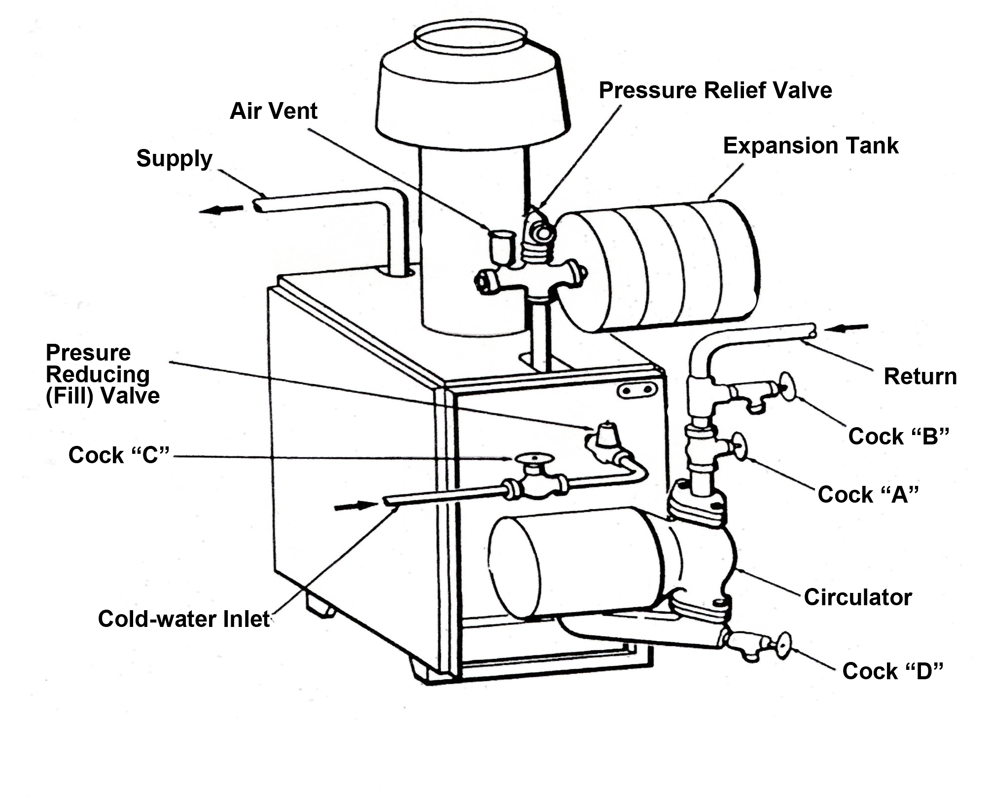
Above is an example of a typical gas package boiler of the 1950’s up to the present.
Before we get too involved, we need an explanation for the designations of control series. When the heating control industry began coming into its own many years ago, Honeywell was one of the early pioneers. They developed control systems to cover a broad spectrum including gravity warm air systems, steam systems and gravity hot water systems. It became necessary to identify controls for how they were wired and their particular switching action, such as SPST,SPDT, etc. These systems were given “series” numbers, such as series 10 or series 20 and so on. What follows is a brief description of several of the systems involved. A few have been obsolete for some time while others remain with us today. To identify which system you’re working with, you only need look at the first digit in the control number. For example, T105 is series 10, T-26 is series 20, etc. Series 20 controls are no longer available today. There are a few series 10 controls still being produced however, such as the RA 117 stack relay for oil or the R-182 relay. While the series 20 controls are no longer available, the power to open power to close concept continues to be used in some vent dampers, zone valves and modulating motors.
Here is a list of control functions that we want to achieve with Forced Hot Water systems:
• Safety
• Maintain Water Temperature
• Circlate Water
• Maintain Space Temperature
Safety is of course always first priority and should never be circumvented for the sake of comfort. We will be discussing the various controls that help us satisfy these basic control functions.
There are three basic rules of forced hot water systems that simplify our understanding of what can be accomplished. No matter how complex the system, these three rules will remain present consistently. The only exception involves rule three, which does not apply if we do not have a demand for domestic hot water. When the thermostat calls for heat, the burner and circulator turn on together.
This has been the case for many years. As of September 1, 2012, the three basic rules were altered based on a DOE (Department of Energy) rule. In simple terms it states: The boiler looks for 140ºF water temperature or a two minute time limit, whichever comes first, and then fires the burner. If the boiler water is 140ºF or higher then the circulator alone should be running. The boiler burners should only be on when the boiler water is below 140ºF.
• If the boiler goes off while on limit, the circulator will continue to run.
• The domestic Aquastat or Low Limit always has priority over heating.
2012 Residential Boiler Standards
On September 1, 2012, the residential boiler minimum federal efficiency standards went into effect. The standards (set by the Federal Independence & Security Act [EISA] in 2007 then fully implemented Sept. 1, 2012) required residential gas hot water boilers to meet a minimum AFUE of 82%; gas steam boilers, 80%; oil hot water boilers, 84%; and oil steam boilers, 82%.
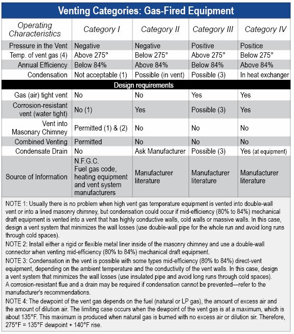
Most of our new equipment today is classified either as a Category III or IV. A Category III is a system with a positive vent pressure, a stack temperature above 275°F, annual efficiency below 84%, and with the potential for condensing in the flue (usually a stainless steel flue is required). It can’t be vented into a chimney so is typically side-wall vented. It is usually called mid-efficiency equipment.
Category IV also involves a positive pressure in the vent with its stack temperature below 275°F, vented with Poly Pro special venting material. This author does not recommend the use of PVC or CPVC as a vent with equipment, but they can be used as an air intake pipe. By design, these will cause condensation in the heat exchanger. The approach is often called high efficiency equipment with an AFUE above 84%.
Modern forced hot water systems, coupled with 24 volt standing pilot systems, is a system which both modulates and acts as a condensing appliance. Modulation is typically accomplished by varying the combustion air blower speed, which then in conjunction with a negative pressure gas valve causes gas to be premixed with the air varying input to the equipment. Most systems on the residential side have a 5-to-1 turn down ratio. Put another way, a 100,000 BTU piece of equipment would fire from 20,000 on the low end up to 100,000 on the high end with increments in between 40,000, 60,000, and 80,000. Some new equipment now has a ten to one ratio available on residential systems.
Condensation is accomplished by keeping the stack temperature below 275°F and the return water temperature (in the case of boilers) maintained at 140°F or less. The system is designed to allow condensation to take place in the boiler heat exchanger. This, of course, was new allowable on cast iron and steel boilers since it would cause corrosion within the boiler sections.
The following points offer some subjects to consider when looking at installing a Mod/Con to replace your existing, dated boiler with either gas or oil. They are not presented in any particular order, all are important.
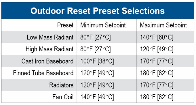
•What kind of radiation does the existing system have (baseboard, convectors, radiators)? Most of these are designed to operate above 180°F, so the installer needs to consider whether say in the case of baseboards they are designed to give 600 BTUs per lineal foot at 180°, for example. Will a temperature below 140° adequately heat the dwelling? More baseboards may need to be added in order to meet the room BTU heat loss.
•Can this type of system be used on an old gravity hot water system? With some piping changes it can be done and definitely requires outdoor reset and mixing controls.
•Water temperatures become important as some manufacturers have a high limit of approximately 165°F as a maximum temp on their boilers.
•Did heat loss occur? If so, do not trust the previous inputs on older equipment.
•Piping changes to primary secondary, of a low loss header.
•Water temperature mixing certainly in the case of domestic hot water applications.
•Complexity of control systems. It’s worthwhile to keep things as simple as you can.
•Make sure you know that annual maintenance is required on these systems. These are not your old gas boilers, which required very little maintenance. Let the customer know about annual requirements and their cost.
•What is the preferred type of boiler heat exchanger? Stainless steel, cast aluminum, cast iron, something else? All of these are available from different manufacturers for use on condensing equipment.
•How is domestic hot water going to be supplied? On demand, indirect, or storage?
•The history on the new equipment as to the performance, problems, etc. ICM
There are not a lot of differences between gas and oil hydronics. The obvious one is the burners and fuels are different. The controls, however, are typically the same with some exceptions. I want to, in this series of articles, address the differences and how to work with them. In addition to the diagnosis and solving of problems on the two different fuel systems, we will briefly address some steam related facts. However, our emphasis will be on Forced Hot Water systems used on gas both Natural and Propane gas.
We will be emphasizing the older systems and not in this series get into Modulating/Condensing equipment. I want to address controls that are unique to gas. Below is an example of a typical gas package boiler of the 1950s still used in the present.
Pumping Away
Systems work better when the compression tank is connected on the suction side of the pump. This is called the “Point of No Pressure Change.” This is the way commercial systems have been installed for years. This typically means that the circulator is installed pumping away from the boiler and toward the systems.
The idea has in recent years caught on with residential and small commercial piping. It was probably not done in the past because no one ever gave people a good reason to change, but now there is a good reason. Just look at all the changes that circulators have gone through over the past few years. These new circulators are smaller and run at higher speeds and higher heads.
That makes a difference in the way the system operates. We have seen so much of a difference, in fact, that we see a brand-new opportunity for you.
When a circulator pumps away from a compression tank (expansion tank), all the circulator’s pressure appears as an increase out in the system. This sudden increase in pressure helps move air out of the radiators. Start-up becomes much easier, and, usually, there are fewer air-related problems from that day on.
On the other hand, when you pump toward a compression tank (typically, when the pump is on the return side of the boiler), the circulator’s pressure appears as a drop in pressure on the circulator’s inlet side.
If you’ve ever piped a feed valve into the inlet side of a circulator on the return side of a boiler, you’ve seen this drop in pressure. The feed valve opens every time the circulator comes on. It can be a real problem.
This sudden drop in system pressure also makes it harder to get the air out of the radiators. System start-up is tougher (especially on one-pipe systems with venturi-type fittings) and, in some cases, air can actually be sucked into the system through the air vents.
No one really noticed this problem with the older circulators, but nowadays, many residential systems are using small, high-speed circulators. These circulators, because of the higher heads they produce, can help you remove system air—if you install them pumping away from the compression tank and toward the system, or they can work against you.
When you install them pumping toward the compression tank, they will drop the system pressure on their inlet side (as much as six psig) every time they come on. That sudden drop in pressure will expand the trapped air bubbles up in the radiators, making it even more difficult to get air out of the system.
Have you ever noticed how it always seems to be those last couple of convectors, the ones closest to the return, which give you the biggest problem on start-up? Now you know why.
Why not use this pressure phenomenon to your advantage? Pump the supply side. The system will work a lot better and you may be amazed at the results. We say this even as we recognize that pumps installed on the return side have worked for years. They’ve even become a tradition. Most of the drawings published over the years show the pumps on the return side and with the low-head pumps, this usually is not a problem. However in light of today’s high-head circulators, we’ve become convinced that your systems will work much better and start up a lot easier if you take this fresh approach of pumping away. It’s good to question habit and tradition from time to time.
Some examples are illustrated:
Below is an example of pumping away with circulator on the supply side, which is the preferred method. The circulator can however be placed on the return and still allow for pumping away from point of no pressure change.
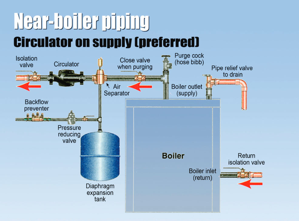
Control Systems
As we go over different controls, all of them will fall into some category of what part of the system they function in or control. This is an example of some that in particular are used in hydronic systems in particular. The listing includes controls also used on forced warm air so that we may have some point of reference.
1. Primary Controls (loads)
A. Is the control that is being controlled by the thermostat or controller.
B. Require power for their operation in:
(1) Gas Valves
(2) Relays
(3) Zone Valves
(4) Zone Dampers
(5) Flue Dampers
2. Operators (operate primary controls) (switches)
A. Thermostat
B. Aquastat
C. Pressuretrol
3. Secondary Controls
A. Pressuretrol (2 lbs off .5 lb on (steam) (hot water
and steam)
B. Low water cut off
C. High limit (warm air) (200°F)
D. High limit (hot water)
E. Low limit
F. Fan Control Normally Open (Closes on a
temperature rise)
G. Reverse acting control (pump aquastat, circulator
control)
4. Loads
A. Relay coil
B. Motors
C. Transformers (primary load) (secondary source)
When it comes to setting temperatures for forced hot water conventional systems, the Incorporation by Reference (IBR) handbook suggest settings follow.
Settings for different systems
STEAM: Pressuretrol: 2 lbs. off–.5 lb. on (on normal household jobs)
VAPOR: Vaporstat: 8 oz. off–2 oz. on (unless engineer gives different setting)
FORCED WARM AIR: Combination fan and limit control
Limit: 200°
Fan on: 125°
Fan off: 110°
(if separate controls, set accordingly)
GRAVITY WARM AIR: Airstat Limit
control: 250°
GRAVITY HOT WATER: Aquastat Limit
control: 140°–150°
FORCED HOT WATER: High Limit control: 185°
(for radiators) 200° (for convectors)
210°–215° (baseboard radiation)
Low limit control: 150°
Circulator control: 120°–125°
(If there is a combination control with low limit and
reverse on the same setting, set the low limit to 150°and the differential to 25°).
AUXILLARY LIMITS
STEAM: Pressuretrol: 2 lbs off–.5 lb on.
Auxiliary pressuretrol:14 lbs off–
(set cut in to nine and differential to five) 9 lbs on.
HOT WATER: High limit 180°
Auxiliary high limit 220°
Thanks to Dan Holohan for the information on pumping away. Contact him at HeatingHelp.com.